DirectX Graphics提供的编程接口包括Direct3D组件和D3DX扩展组件,利用DirectX Graphics可以一致地处理二维和三维的图形渲染,而不再需要应用早期DirectX版本下的DirectDraw组件进行二维图形的显示处理。
DirectX Graphics基本应用架构
首
先来看看三维物体的成像过程。三维物体可通过建模的微分方法,把弯曲的表面切分为一个个的三角形面,这样三维物体表面的绘制,就转化为物体表面中所有三角
形面的绘制。要渲染由众多三维物体组成的三维场景,需要先引入局部坐标系,为场景中的各个三维物体进行三角形顶点的坐标量化。
引入世界坐
标系,把整个场景中所有的三维物体的各自顶点局部坐标,转换为同一个世界坐标系下的坐标。在同一个世界坐标系中,场景中各个三角形面的顶点坐标如实地给出
了场景中物体间的空间关系。如果需要对场景实施光照处理,还要对顶点的颜色值进行计算,这个过程最终输出具有世界坐标的场景下的所有三维物体的顶点信息。
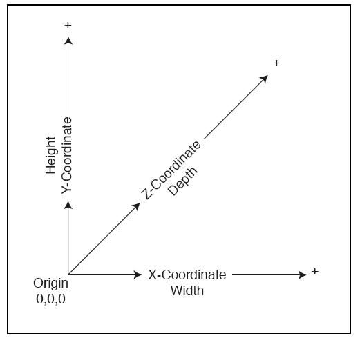
如下所示,三维坐标系X,Y,Z。X和Y是对显示器的模拟,而Z坐标表示了显示器或所显示图像的深度。
在
三维场景中选定位置和方向架设摄影机,取景范围由一个棱台视截体决定。在视截体之内的部分应显示处理,视截体之外的部分则要剪裁掉不显示出来。为了便于剪
裁,在摄影机的位置处建立一个摄影坐标系,其Z轴指向摄影机的视线方向,从而使视截体的6个外围侧面具有较为简单的方程式。此时,需要将场景中所有物体的
三角形顶点的世界坐标转换为摄影坐标系下的坐标。这个过程最终输出变换为摄影坐标的顶点信息。
取得场景中所有物体的三角形顶点的摄影坐标
之后,开始进行剪裁和透视投影处理。先将视截体投影变换为一个[-1, 1] x [-1, 1] x [0,
1]的方体,这样顶点是否位于视觉范围内,就可以通过-1<x<1, -1<y<1,
0<z<1的简单式子进行判断。另一方面,通过立方体的一个XOY截面,取得场景中三维物体的顶点在同一个平面上的投影图的
X和Y投影坐标,而保留顶点原来的Z坐标值,以反映三维物体间的远近关系。这个过程最终输出位于视觉区域内,并且已变换为投影坐标的顶点信息。
将
平面投影的点变换到计算机屏幕的视口中,并根据投影点的Z坐标值反映的顶点远近遮隐关系,确定屏幕视口中各个像素的颜色值,以此实现三维场景的平面着色显
示。如果采用纹理贴图等特效处理,还需要进一步对视口的像素值进行混色计算。这个过程最终输出的是提交显卡显示的三维场景的二维像素颜色信息。
Direct3D API通过中间层的硬件抽象层HAL调用显卡驱动程序,解决了与硬件无关的问题。DirectX 9.0所实现硬件抽象层HAL包含三种顶点处理模式:硬件顶点处理模式,软件顶点处理模式,以及硬件和软件混合处理模式。
大致的调用层次关系如下所示:
Win32应用程序 <---> Direct3D API <---> HAL <---> 显卡驱动程序 <---> 显卡
对
于支持三维图形渲染的显卡来说,上面所描述的三维物体的成像算法,基本上将相关的处理代码以固化代码的形式封装在显卡中,Direct3D
API的任务就是接受请求,然后通过下面各层所提供的服务,转而调用显卡固化的渲染代码。当显卡不支持3D图形处理,可考虑使用硬件抽象层的软件顶点处理
模式进行3D渲染,但是这种模式的执行速度相对较慢。硬件抽象层HAL的上层Direct3D API提供了一种统一的形式处理硬件或软件的3D渲染。
创建IDirect3D9接口对象
使用 DirectGraphics组件进行渲染,同样也要先创建一个IDirect3D9接口对象,再创建一个Direct3D设备,然后利用 Direct3D设备的接口方法操控管道流水线进行三维图形的渲染。
创建IDirect3D9接口对象的函数为 Direct3DCreate9,来看看MSDN提供的该函数使用信息:
Create a IDirect3D9 object and returns an interace to it.
Syntax
IDirect3D9 *WINAPI Direct3DCreate9(UINT SDKVersion);
Parameters
SDKVersion
The value of this parameter should be D3D_SDK_VERSION. See Remarks.
Return Value
If successful, this function returns a pointer to an IDirect3D9 interface; otherwise, a NULL pointer is returned.
Remarks
The Microsoft Direct3D object is the first object that your application creates and the last object
that your application releases. Functions for enumerating and retrieving capabilities of a Direct3D
device are accessible through the Direct3D object. This enables applications to select devices
without creating them.
Create a IDirect3D9 object as shown here:
LPDIRECT3D9 g_pD3D = NULL;
if( NULL == (g_pD3D = Direct3DCreate9(D3D_SDK_VERSION)))
return E_FAIL;
A IDirect3D9 interface supports enumeration of active display adapters and allows the creation of
IDirect3DDevice9 objects. If the user dynamically adds adapters (either by adding devices to the
desktop, or by hot-docking a laptop), those devices will not be included in the enumeration.
Creating a new IDirect3D9 interface will expose the new devices.
D3D_SDK_VERSION is passed to this function to ensure that the header files against which an application
is compiled match the version of the runtime dynamic-link library (DLL)'s that are installed on the machine.
D3D_SDK_VERSION is only changed in the runtime when a header change (or other code change) would
require an application to be rebuilt. If this function fails, it indicates that the header file version does not
match the runtime DLL version. See GetDXVer Sample for help checking the version of the runtime that is
installed on your machine.创建Direct3D设备创建Direct3D设备之前,首先需要检查当前显卡是否支持3D顶点的硬件渲染,以决定Direct3D API应使用硬件抽象层HAL的哪种模式进行调用。
IDirect3D9接口对象的GetDeviceCaps 函数提供了显卡的功能检测,该函数返回一个D3DCAPS9类型的信息,来看看MSDN提供的关于该函数的使用信息:
Retrieves device-specific information about a device.
Syntax
HRESULT GetDeviceCaps( UINT Adapter,
D3DDEVTYPE DeviceType,
D3DCAPS9 *pCaps
);
Parameters
Adapter
[in] Ordinal number that denotes the display adapter. D3DADAPTER_DEFAULT is always the primary display adapter.
DeviceType
[in] Member of the D3DDEVTYPE enumerated type. Denotes the device type.
pCaps
[out] Pointer to a D3DCAPS9 structure to be filled with information describing the capabilities of the device.
Return Value
If the method succeeds, the return value is D3D_OK.
If the method fails, the return value can be one of the following values.
D3DERR_INVALIDCALL The method call is invalid. For example, a method's parameter may have an invalid value.
D3DERR_INVALIDDEVICE The requested device type is not valid.
D3DERR_OUTOFVIDEOMEMORY Direct3D does not have enough display memory to perform the operation.
Remarks
The application should not assume the persistence of vertex processing capabilities across Microsoft
Direct3D device objects. The particular capabilities that a physical device exposes may depend on
parameters supplied to IDirect3D9::CreateDevice. For example, the capabilities may yield different
vertex processing capabilities before and after creating a Direct3D Device Object with hardware vertex
processing enabled. For more information see the description of D3DCAPS9.
我们来看看第二个参数类型
D3DDEVTYPE的相关信息:
Defines device types.
Syntax
typedef enum _D3DDEVTYPE {
D3DDEVTYPE_HAL = 1,
D3DDEVTYPE_NULLREF = 4,
D3DDEVTYPE_REF = 2,
D3DDEVTYPE_SW = 3,
D3DDEVTYPE_FORCE_DWORD = 0xffffffff
} D3DDEVTYPE;
Constants
D3DDEVTYPE_HAL
Hardware rasterization. Shading is done with software, hardware, or mixed transform and lighting.
D3DDEVTYPE_NULLREF
Initialize Microsoft Direct3D on a computer that has neither hardware nor reference rasterization available,
and enable resources for 3-D content creation. See Remarks.
D3DDEVTYPE_REF
Direct3D features are implemented in software; however, the reference rasterizer does make use of special CPU
instructions whenever it can.
D3DDEVTYPE_SW
A pluggable software device that has been registered with IDirect3D9::RegisterSoftwareDevice.
D3DDEVTYPE_FORCE_DWORD
Forces this enumeration to compile to 32 bits in size. Without this value, some compilers would allow this enumeration
to compile to a size other than 32 bits. This value is not used.
Remarks
All methods of the IDirect3D9 interface that take a D3DDEVTYPE device type will fail if D3DDEVTYPE_NULLREF
is specified. To use these methods, substitute D3DDEVTYPE_REF in the method call.
A D3DDEVTYPE_REF device should be created in D3DPOOL_SCRATCH memory, unless vertex and index buffers are
required. To support vertex and index buffers, create the device in D3DPOOL_SYSTEMMEM memory.
If D3dref9.dll is installed, Direct3D will use the reference rasterizer to create a D3DDEVTYPE_REF device type,
even if D3DDEVTYPE_NULLREF is specified. If D3dref9.dll is not available and D3DDEVTYPE_NULLREF is specified,
Direct3D will neither render nor present the scene.
D3DCAPS9是一个结构体,用于存放当前设备类型下的各种硬件属性和功能,看看它的具体信息:
Represents the capabilities of the hardware exposed through the Direct3D
object.
typedef struct D3DCAPS9 {
    D3DDEVTYPE DeviceType;
    UINT AdapterOrdinal;
    DWORD Caps;
    DWORD Caps2;
    DWORD Caps3;
    DWORD PresentationIntervals;
    DWORD CursorCaps;
    DWORD DevCaps;
    DWORD PrimitiveMiscCaps;
    DWORD RasterCaps;
    DWORD ZCmpCaps;
    DWORD SrcBlendCaps;
    DWORD DestBlendCaps;
    DWORD AlphaCmpCaps;
    DWORD ShadeCaps;
    DWORD TextureCaps;
    DWORD TextureFilterCaps;
    DWORD CubeTextureFilterCaps;
    DWORD VolumeTextureFilterCaps;
    DWORD TextureAddressCaps;
    DWORD VolumeTextureAddressCaps;
    DWORD LineCaps;
    DWORD MaxTextureWidth;
    DWORD MaxTextureHeight;
    DWORD MaxVolumeExtent;
    DWORD MaxTextureRepeat;
    DWORD MaxTextureAspectRatio;
    DWORD MaxAnisotropy;
    float MaxVertexW;
    float GuardBandLeft;
    float GuardBandTop;
    float GuardBandRight;
    float GuardBandBottom;
    float ExtentsAdjust;
    DWORD StencilCaps;
    DWORD FVFCaps;
    DWORD TextureOpCaps;
    DWORD MaxTextureBlendStages;
    DWORD MaxSimultaneousTextures;
    DWORD VertexProcessingCaps;
    DWORD MaxActiveLights;
    DWORD MaxUserClipPlanes;
    DWORD MaxVertexBlendMatrices;
    DWORD MaxVertexBlendMatrixIndex;
    float MaxPointSize;
    DWORD MaxPrimitiveCount;
    DWORD MaxVertexIndex;
    DWORD MaxStreams;
    DWORD MaxStreamStride;
    DWORD VertexShaderVersion;
    DWORD MaxVertexShaderConst;
    DWORD PixelShaderVersion;
    float PixelShader1xMaxValue;
    DWORD DevCaps2;
    UINT MasterAdapterOrdinal;
    UINT AdapterOrdinalInGroup;
    UINT NumberOfAdaptersInGroup;
    DWORD DeclTypes;
    DWORD NumSimultaneousRTs;
    DWORD StretchRectFilterCaps;
    D3DVSHADERCAPS2_0 VS20Caps;
    D3DPSHADERCAPS2_0 D3DPSHADERCAPS2_0;
    DWORD VertexTextureFilterCaps;
    DWORD MaxVShaderInstructionsExecuted;
    DWORD MaxPShaderInstructionsExecuted;
    DWORD MaxVertexShader30InstructionSlots;
    DWORD MaxPixelShader30InstructionSlots;
    DWORD Reserved2;
    DWORD Reserved3;
} D3DCAPS9, *LPD3DCAPS9;
Members
- DeviceType
- Member of the D3DDEVTYPE enumerated type, which identifies what type of
resources are used for processing vertices.
- AdapterOrdinal
- Adapter on which this Direct3D device was created. This ordinal is valid
only to pass to methods of the IDirect3D9 interface that created this
Direct3D device. The IDirect3D9 interface can always be retrieved by
calling IDirect3DDevice9::GetDirect3D.
- Caps
- The following driver-specific capability.
- D3DCAPS_READ_SCANLINE
- Display hardware is capable of returning the current scan line.
- Caps2
- Driver-specific capabilities identified in D3DCAPS2.
- Caps3
- Driver-specific capabilities identified in D3DCAPS3.
- PresentationIntervals
- Bit mask of values representing what presentation swap intervals are
available.
- D3DPRESENT_INTERVAL_IMMEDIATE
- The driver supports an immediate presentation swap interval.
- D3DPRESENT_INTERVAL_ONE
- The driver supports a presentation swap interval of every screen
refresh.
- D3DPRESENT_INTERVAL_TWO
- The driver supports a presentation swap interval of every second
screen refresh.
- D3DPRESENT_INTERVAL_THREE
- The driver supports a presentation swap interval of every third
screen refresh.
- D3DPRESENT_INTERVAL_FOUR
- The driver supports a presentation swap interval of every fourth
screen refresh.
- CursorCaps
- Bit mask indicating what hardware support is available for cursors.
Direct3D 9 does not define alpha-blending cursor capabilities.
- D3DCURSORCAPS_COLOR
- A full-color cursor is supported in hardware. Specifically, this
flag indicates that the driver supports at least a hardware color cursor
in high-resolution modes (with scan lines greater than or equal to 400).
- D3DCURSORCAPS_LOWRES
- A full-color cursor is supported in hardware. Specifically, this
flag indicates that the driver supports a hardware color cursor in both
high-resolution and low-resolution modes (with scan lines less than
400).
- DevCaps
- Flags identifying the capabilities of the device.
- D3DDEVCAPS_CANBLTSYSTONONLOCAL
- Device supports blits from system-memory textures to nonlocal
video-memory textures.
- D3DDEVCAPS_CANRENDERAFTERFLIP
- Device can queue rendering commands after a page flip. Applications
do not change their behavior if this flag is set; this capability means
that the device is relatively fast.
- D3DDEVCAPS_DRAWPRIMITIVES2
- Device can support at least a DirectX 5-compliant driver.
- D3DDEVCAPS_DRAWPRIMITIVES2EX
- Device can support at least a DirectX 7-compliant driver.
- D3DDEVCAPS_DRAWPRIMTLVERTEX
- Device exports an IDirect3DDevice9::DrawPrimitive-aware hal.
- D3DDEVCAPS_EXECUTESYSTEMMEMORY
- Device can use execute buffers from system memory.
- D3DDEVCAPS_EXECUTEVIDEOMEMORY
- Device can use execute buffers from video memory.
- D3DDEVCAPS_HWRASTERIZATION
- Device has hardware acceleration for scene rasterization.
- D3DDEVCAPS_HWTRANSFORMANDLIGHT
- Device can support transformation and lighting in hardware.
- D3DDEVCAPS_NPATCHES
- Device supports N patches.
- D3DDEVCAPS_PUREDEVICE
- Device can support rasterization, transform, lighting, and shading
in hardware.
- D3DDEVCAPS_QUINTICRTPATCHES
- Device supports quintic Bézier curves and B-splines.
- D3DDEVCAPS_RTPATCHES
- Device supports rectangular and triangular patches.
- D3DDEVCAPS_RTPATCHHANDLEZERO
- When this device capability is set, the hardware architecture does
not require caching of any information, and uncached patches (handle
zero) will be drawn as efficiently as cached ones. Note that setting
D3DDEVCAPS_RTPATCHHANDLEZERO does not mean that a patch with handle zero
can be drawn. A handle-zero patch can always be drawn whether this cap
is set or not.
- D3DDEVCAPS_SEPARATETEXTUREMEMORIES
- Device is texturing from separate memory pools.
- D3DDEVCAPS_TEXTURENONLOCALVIDMEM
- Device can retrieve textures from non-local video memory.
- D3DDEVCAPS_TEXTURESYSTEMMEMORY
- Device can retrieve textures from system memory.
- D3DDEVCAPS_TEXTUREVIDEOMEMORY
- Device can retrieve textures from device memory.
- D3DDEVCAPS_TLVERTEXSYSTEMMEMORY
- Device can use buffers from system memory for transformed and lit
vertices.
- D3DDEVCAPS_TLVERTEXVIDEOMEMORY
- Device can use buffers from video memory for transformed and lit
vertices.
- PrimitiveMiscCaps
- Miscellaneous driver primitive capabilities. See D3DPMISCCAPS.
- RasterCaps
- Information on raster-drawing capabilities. This member can be one or
more of the following flags.
- D3DPRASTERCAPS_ANISOTROPY
- Device supports anisotropic filtering.
- D3DPRASTERCAPS_COLORPERSPECTIVE
- Device iterates colors perspective correctly.
- D3DPRASTERCAPS_DITHER
- Device can dither to improve color resolution.
- D3DPRASTERCAPS_DEPTHBIAS
- Device supports legacy depth bias. For true depth bias, see
D3DPRASTERCAPS_SLOPESCALEDEPTHBIAS.
- D3DPRASTERCAPS_FOGRANGE
- Device supports range-based fog. In range-based fog, the distance of
an object from the viewer is used to compute fog effects, not the depth
of the object (that is, the z-coordinate) in the scene.
- D3DPRASTERCAPS_FOGTABLE
- Device calculates the fog value by referring to a lookup table
containing fog values that are indexed to the depth of a given pixel.
- D3DPRASTERCAPS_FOGVERTEX
- Device calculates the fog value during the lighting operation and
interpolates the fog value during rasterization.
- D3DPRASTERCAPS_MIPMAPLODBIAS
- Device supports level-of-detail bias adjustments. These bias
adjustments enable an application to make a mipmap appear crisper or
less sharp than it normally would. For more information about
level-of-detail bias in mipmaps, see D3DSAMP_MIPMAPLODBIAS.
- D3DPRASTERCAPS_MULTISAMPLE_TOGGLE
- Device supports toggling multisampling on and off between
IDirect3DDevice9::BeginScene and IDirect3DDevice9::EndScene (using
D3DRS_MULTISAMPLEANTIALIAS).
- D3DPRASTERCAPS_SCISSORTEST
- Device supports scissor test. See Scissor Test (Direct3D 9).
- D3DPRASTERCAPS_SLOPESCALEDEPTHBIAS
- Device performs true slope-scale based depth bias. This is in
contrast to the legacy style depth bias.
- D3DPRASTERCAPS_WBUFFER
- Device supports depth buffering using w.
- D3DPRASTERCAPS_WFOG
- Device supports w-based fog. W-based fog is used when a perspective
projection matrix is specified, but affine projections still use z-based
fog. The system considers a projection matrix that contains a nonzero
value in the [3][4] element to be a perspective projection matrix.
- D3DPRASTERCAPS_ZBUFFERLESSHSR
- Device can perform hidden-surface removal (HSR) without requiring
the application to sort polygons and without requiring the allocation of
a depth-buffer. This leaves more video memory for textures. The method
used to perform HSR is hardware-dependent and is transparent to the
application.
Z-bufferless HSR is performed if no depth-buffer surface is
associated with the rendering-target surface and the depth-buffer
comparison test is enabled (that is, when the state value associated
with the D3DRS_ZENABLE enumeration constant is set to TRUE).
- D3DPRASTERCAPS_ZFOG
- Device supports z-based fog.
- D3DPRASTERCAPS_ZTEST
- Device can perform z-test operations. This effectively renders a
primitive and indicates whether any z pixels have been rendered.
- ZCmpCaps
- Z-buffer comparison capabilities. This member can be one or more of the
following flags.
- D3DPCMPCAPS_ALWAYS
- Always pass the z-test.
- D3DPCMPCAPS_EQUAL
- Pass the z-test if the new z equals the current z.
- D3DPCMPCAPS_GREATER
- Pass the z-test if the new z is greater than the current z.
- D3DPCMPCAPS_GREATEREQUAL
- Pass the z-test if the new z is greater than or equal to the current
z.
- D3DPCMPCAPS_LESS
- Pass the z-test if the new z is less than the current z.
- D3DPCMPCAPS_LESSEQUAL
- Pass the z-test if the new z is less than or equal to the current z.
- D3DPCMPCAPS_NEVER
- Always fail the z-test.
- D3DPCMPCAPS_NOTEQUAL
- Pass the z-test if the new z does not equal the current z.
- SrcBlendCaps
- Source-blending capabilities. This member can be one or more of the
following flags. (The RGBA values of the source and destination are
indicated by the subscripts s and d.)
- D3DPBLENDCAPS_BLENDFACTOR
- The driver supports both D3DBLEND_BLENDFACTOR and
D3DBLEND_INVBLENDFACTOR. See D3DBLEND.
- D3DPBLENDCAPS_BOTHINVSRCALPHA
- Source blend factor is (1 - As, 1 - As, 1 - As,
1 - As) and destination blend factor is (As, As,
As, As); the destination blend selection is
overridden.
- D3DPBLENDCAPS_BOTHSRCALPHA
- The driver supports the D3DBLEND_BOTHSRCALPHA blend mode. (This
blend mode is obsolete. For more information, see D3DBLEND.)
- D3DPBLENDCAPS_DESTALPHA
- Blend factor is (Ad, Ad, Ad, Ad).
- D3DPBLENDCAPS_DESTCOLOR
- Blend factor is (Rd, Gd, Bd, Ad).
- D3DPBLENDCAPS_INVDESTALPHA
- Blend factor is (1 - Ad, 1 - Ad, 1 - Ad,
1 - Ad).
- D3DPBLENDCAPS_INVDESTCOLOR
- Blend factor is (1-Rd, 1-Gd, 1-Bd,
1 - Ad).
- D3DPBLENDCAPS_INVSRCALPHA
- Blend factor is (1 - As, 1 - As, 1 - As,
1 - As).
- D3DPBLENDCAPS_INVSRCCOLOR
- Blend factor is (1-Rs, 1-Gs, 1-Bs,
1 - As).
- D3DPBLENDCAPS_ONE
- Blend factor is (1, 1, 1, 1).
- D3DPBLENDCAPS_SRCALPHA
- Blend factor is (As, As, As, As).
- D3DPBLENDCAPS_SRCALPHASAT
- Blend factor is (f, f, f, 1); f = min(As, 1 - Ad).
- D3DPBLENDCAPS_SRCCOLOR
- Blend factor is (Rs, Gs, Bs, As).
- D3DPBLENDCAPS_ZERO
- Blend factor is (0, 0, 0, 0).
- DestBlendCaps
- Destination-blending capabilities. This member can be the same
capabilities that are defined for the SrcBlendCaps member.
- AlphaCmpCaps
- Alpha-test comparison capabilities. This member can include the same
capability flags defined for the ZCmpCaps member. If this member contains
only the D3DPCMPCAPS_ALWAYS capability or only the D3DPCMPCAPS_NEVER
capability, the driver does not support alpha tests. Otherwise, the flags
identify the individual comparisons that are supported for alpha testing.
- ShadeCaps
- Shading operations capabilities. It is assumed, in general, that if a
device supports a given command at all, it supports the D3DSHADE_FLAT mode
(as specified in the D3DSHADEMODE enumerated type). This flag specifies
whether the driver can also support Gouraud shading and whether alpha color
components are supported. When alpha components are not supported, the alpha
value of colors generated is implicitly 255. This is the maximum possible
alpha (that is, the alpha component is at full intensity).
The color, specular highlights, fog, and alpha interpolants of a triangle
each have capability flags that an application can use to find out how they
are implemented by the device driver.
This member can be one or more of the following flags.
- D3DPSHADECAPS_ALPHAGOURAUDBLEND
- Device can support an alpha component for Gouraud-blended
transparency (the D3DSHADE_GOURAUD state for the D3DSHADEMODE
enumerated type). In this mode, the alpha color component of a primitive
is provided at vertices and interpolated across a face along with the
other color components.
- D3DPSHADECAPS_COLORGOURAUDRGB
- Device can support colored Gouraud shading. In this mode, the
per-vertex color components (red, green, and blue) are interpolated
across a triangle face.
- D3DPSHADECAPS_FOGGOURAUD
- Device can support fog in the Gouraud shading mode.
- D3DPSHADECAPS_SPECULARGOURAUDRGB
- Device supports Gouraud shading of specular highlights.
- TextureCaps
- Miscellaneous texture-mapping capabilities. This member can be one or
more of the following flags.
- D3DPTEXTURECAPS_ALPHA
- Alpha in texture pixels is supported.
- D3DPTEXTURECAPS_ALPHAPALETTE
- Device can draw alpha from texture palettes.
- D3DPTEXTURECAPS_CUBEMAP
- Supports cube textures.
- D3DPTEXTURECAPS_CUBEMAP_POW2
- Device requires that cube texture maps have dimensions specified as
powers of two.
- D3DPTEXTURECAPS_MIPCUBEMAP
- Device supports mipmapped cube textures.
- D3DPTEXTURECAPS_MIPMAP
- Device supports mipmapped textures.
- D3DPTEXTURECAPS_MIPVOLUMEMAP
- Device supports mipmapped volume textures.
- D3DPTEXTURECAPS_NONPOW2CONDITIONAL
- D3DPTEXTURECAPS_POW2 is also set, conditionally supports the use of
2D textures with dimensions that are not powers of two. A device that
exposes this capability can use such a texture if all of the following
requirements are met.
- The texture addressing mode for the texture stage is set to
D3DTADDRESS_CLAMP.
- Texture wrapping for the texture stage is disabled (D3DRS_WRAP
n set to 0).
- Mipmapping is not in use (use magnification filter only).
- Texture formats must not be D3DFMT_DXT1 through D3DFMT_DXT5.
If this flag is not set, and D3DPTEXTURECAPS_POW2 is also not set,
then unconditional support is provided for 2D textures with dimensions
that are not powers of two.
A texture that is not a power of two cannot be set at a stage that
will be read based on a shader computation (such as the bem - ps and
texm3x3 - ps instructions in pixel shaders versions 1_0 to 1_3). For
example, these textures can be used to store bumps that will be fed into
texture reads, but not the environment maps that are used in texbem - ps,
texbeml - ps, and texm3x3spec - ps. This means that a texture with
dimensions that are not powers of two cannot be addressed or sampled
using texture coordinates computed within the shader. This type of
operation is known as a dependent read and cannot be performed on these
types of textures.
- D3DPTEXTURECAPS_NOPROJECTEDBUMPENV
- Device does not support a projected bump-environment loopkup
operation in programmable and fixed function shaders.
- D3DPTEXTURECAPS_PERSPECTIVE
- Perspective correction texturing is supported.
- D3DPTEXTURECAPS_POW2
- If D3DPTEXTURECAPS_NONPOW2CONDITIONAL is not set, all textures must
have widths and heights specified as powers of two. This requirement
does not apply to either cube textures or volume textures.
If
D3DPTEXTURECAPS_NONPOW2CONDITIONAL is also set, conditionally supports
the use of 2D textures with dimensions that are not powers of two. See
D3DPTEXTURECAPS_NONPOW2CONDITIONAL description.
If this flag is not set, and D3DPTEXTURECAPS_NONPOW2CONDITIONAL is
also not set, then unconditional support is provided for 2D textures
with dimensions that are not powers of two.
- D3DPTEXTURECAPS_PROJECTED
- Supports the D3DTTFF_PROJECTED texture transformation flag. When
applied, the device divides transformed texture coordinates by the last
texture coordinate. If this capability is present, then the projective
divide occurs per pixel. If this capability is not present, but the
projective divide needs to occur anyway, then it is performed on a
per-vertex basis by the Direct3D runtime.
- D3DPTEXTURECAPS_SQUAREONLY
- All textures must be square.
- D3DPTEXTURECAPS_TEXREPEATNOTSCALEDBYSIZE
- Texture indices are not scaled by the texture size prior to
interpolation.
- D3DPTEXTURECAPS_VOLUMEMAP
- Device supports volume textures.
- D3DPTEXTURECAPS_VOLUMEMAP_POW2
- Device requires that volume texture maps have dimensions specified
as powers of two.
- TextureFilterCaps
- Texture-filtering capabilities for a texture. Per-stage filtering
capabilities reflect which filtering modes are supported for texture stages
when performing multiple-texture blending. This member can be any
combination of the per-stage texture-filtering flags defined in
D3DPTFILTERCAPS.
- CubeTextureFilterCaps
- Texture-filtering capabilities for a cube texture. Per-stage filtering
capabilities reflect which filtering modes are supported for texture stages
when performing multiple-texture blending. This member can be any
combination of the per-stage texture-filtering flags defined in
D3DPTFILTERCAPS.
- VolumeTextureFilterCaps
- Texture-filtering capabilities for a volume texture. Per-stage filtering
capabilities reflect which filtering modes are supported for texture stages
when performing multiple-texture blending. This member can be any
combination of the per-stage texture-filtering flags defined in
D3DPTFILTERCAPS.
- TextureAddressCaps
- Texture-addressing capabilities for texture objects. This member can be
one or more of the following flags.
- D3DPTADDRESSCAPS_BORDER
- Device supports setting coordinates outside the range [0.0, 1.0] to
the border color, as specified by the D3DSAMP_BORDERCOLOR texture-stage
state.
- D3DPTADDRESSCAPS_CLAMP
- Device can clamp textures to addresses.
- D3DPTADDRESSCAPS_INDEPENDENTUV
- Device can separate the texture-addressing modes of the u and v
coordinates of the texture. This ability corresponds to the
D3DSAMP_ADDRESSU and D3DSAMP_ADDRESSV render-state values.
- D3DPTADDRESSCAPS_MIRROR
- Device can mirror textures to addresses.
- D3DPTADDRESSCAPS_MIRRORONCE
- Device can take the absolute value of the texture coordinate (thus,
mirroring around 0) and then clamp to the maximum value.
- D3DPTADDRESSCAPS_WRAP
- Device can wrap textures to addresses.
- VolumeTextureAddressCaps
- Texture-addressing capabilities for a volume texture. This member can be
one or more of the flags defined for the TextureAddressCaps member.
- LineCaps
- Defines the capabilities for line-drawing primitives.
- D3DLINECAPS_ALPHACMP
- Supports alpha-test comparisons.
- D3DLINECAPS_ANTIALIAS
- Antialiased lines are supported.
- D3DLINECAPS_BLEND
- Supports source-blending.
- D3DLINECAPS_FOG
- Supports fog.
- D3DLINECAPS_TEXTURE
- Supports texture-mapping.
- D3DLINECAPS_ZTEST
- Supports z-buffer comparisons.
- MaxTextureWidth
- Maximum texture width for this device.
- MaxTextureHeight
- Maximum texture height for this device.
- MaxVolumeExtent
- Maximum value for any of the three dimensions (width, height, and depth)
of a volume texture.
- MaxTextureRepeat
- This number represents the maximum range of the integer bits of the
post-normalized texture coordinates. A texture coordinate is stored as a
32-bit signed integer using 27 bits to store the integer part and 5 bits for
the floating point fraction. The maximum integer index, 227, is
used to determine the maximum texture coordinate, depending on how the
hardware does texture-coordinate scaling.
Some hardware reports the cap D3DPTEXTURECAPS_TEXREPEATNOTSCALEDBYSIZE.
For this case, the device defers scaling texture coordinates by the texture
size until after interpolation and application of the texture address mode,
so the number of times a texture can be wrapped is given by the integer
value in MaxTextureRepeat.
Less desirably, on some hardware D3DPTEXTURECAPS_TEXREPEATNOTSCALEDBYSIZE
is not set and the device scales the texture coordinates by the texture size
(using the highest level of detail) prior to interpolation. This limits the
number of times a texture can be wrapped to MaxTextureRepeat / texture size.
For example, assume that MaxTextureRepeat is equal to 32k and the size of
the texture is 4k. If the hardware sets
D3DPTEXTURECAPS_TEXREPEATNOTSCALEDBYSIZE, then the number of times a texture
can be wrapped is equal to MaxTextureRepeat, which is 32k in this example.
Otherwise, the number of times a texture can be wrapped is equal to
MaxTextureRepeat divided by texture size, which is 32k/4k in this example.
- MaxTextureAspectRatio
- Maximum texture aspect ratio supported by the hardware, typically a
power of 2.
- MaxAnisotropy
- Maximum valid value for the D3DSAMP_MAXANISOTROPY texture-stage state.
- MaxVertexW
- Maximum W-based depth value that the device supports.
- GuardBandLeft
- Screen-space coordinate of the guard-band clipping region. Coordinates
inside this rectangle but outside the viewport rectangle are automatically
clipped.
- GuardBandTop
- Screen-space coordinate of the guard-band clipping region. Coordinates
inside this rectangle but outside the viewport rectangle are automatically
clipped.
- GuardBandRight
- Screen-space coordinate of the guard-band clipping region. Coordinates
inside this rectangle but outside the viewport rectangle are automatically
clipped.
- GuardBandBottom
- Screen-space coordinate of the guard-band clipping region. Coordinates
inside this rectangle but outside the viewport rectangle are automatically
clipped.
- ExtentsAdjust
- Number of pixels to adjust the extents rectangle outward to accommodate
antialiasing kernels.
- StencilCaps
- Flags specifying supported stencil-buffer operations. Stencil operations
are assumed to be valid for all three stencil-buffer operation render states
(D3DRS_STENCILFAIL, D3DRS_STENCILPASS, and D3DRS_STENCILZFAIL).
For more information, see D3DSTENCILCAPS.
- FVFCaps
- Flexible vertex format capabilities.
- D3DFVFCAPS_DONOTSTRIPELEMENTS
- It is preferable that vertex elements not be stripped. That is, if
the vertex format contains elements that are not used with the current
render states, there is no need to regenerate the vertices. If this
capability flag is not present, stripping extraneous elements from the
vertex format provides better performance.
- D3DFVFCAPS_PSIZE
- Point size is determined by either the render state or the vertex
data. If an FVF is used, point size can come from point size data in the
vertex declaration. Otherwise, point size is determined by the render
state D3DRS_POINTSIZE. If the application provides point size in
both (the render state and the vertex declaration), the vertex data
overrides the render-state data.
- D3DFVFCAPS_TEXCOORDCOUNTMASK
- Masks the low WORD of FVFCaps. These bits, cast to the WORD data
type, describe the total number of texture coordinate sets that the
device can simultaneously use for multiple texture blending. (You can
use up to eight texture coordinate sets for any vertex, but the device
can blend using only the specified number of texture coordinate sets.)
- TextureOpCaps
- Combination of flags describing the texture operations supported by this
device. The following flags are defined.
- D3DTEXOPCAPS_ADD
- The D3DTOP_ADD texture-blending operation is supported.
- D3DTEXOPCAPS_ADDSIGNED
- The D3DTOP_ADDSIGNED texture-blending operation is supported.
- D3DTEXOPCAPS_ADDSIGNED2X
- The D3DTOP_ADDSIGNED2X texture-blending operation is supported.
- D3DTEXOPCAPS_ADDSMOOTH
- The D3DTOP_ADDSMOOTH texture-blending operation is supported.
- D3DTEXOPCAPS_BLENDCURRENTALPHA
- The D3DTOP_BLENDCURRENTALPHA texture-blending operation is
supported.
- D3DTEXOPCAPS_BLENDDIFFUSEALPHA
- The D3DTOP_BLENDDIFFUSEALPHA texture-blending operation is
supported.
- D3DTEXOPCAPS_BLENDFACTORALPHA
- The D3DTOP_BLENDFACTORALPHA texture-blending operation is supported.
- D3DTEXOPCAPS_BLENDTEXTUREALPHA
- The D3DTOP_BLENDTEXTUREALPHA texture-blending operation is
supported.
- D3DTEXOPCAPS_BLENDTEXTUREALPHAPM
- The D3DTOP_BLENDTEXTUREALPHAPM texture-blending operation is
supported.
- D3DTEXOPCAPS_BUMPENVMAP
- The D3DTOP_BUMPENVMAP texture-blending operation is supported.
- D3DTEXOPCAPS_BUMPENVMAPLUMINANCE
- The D3DTOP_BUMPENVMAPLUMINANCE texture-blending operation is
supported.
- D3DTEXOPCAPS_DISABLE
- The D3DTOP_DISABLE texture-blending operation is supported.
- D3DTEXOPCAPS_DOTPRODUCT3
- The D3DTOP_DOTPRODUCT3 texture-blending operation is supported.
- D3DTEXOPCAPS_LERP
- The D3DTOP_LERP texture-blending operation is supported.
- D3DTEXOPCAPS_MODULATE
- The D3DTOP_MODULATE texture-blending operation is supported.
- D3DTEXOPCAPS_MODULATE2X
- The D3DTOP_MODULATE2X texture-blending operation is supported.
- D3DTEXOPCAPS_MODULATE4X
- The D3DTOP_MODULATE4X texture-blending operation is supported.
- D3DTEXOPCAPS_MODULATEALPHA_ADDCOLOR
- The D3DTOP_MODULATEALPHA_ADDCOLOR texture-blending operation is
supported.
- D3DTEXOPCAPS_MODULATECOLOR_ADDALPHA
- The D3DTOP_MODULATECOLOR_ADDALPHA texture-blending operation is
supported.
- D3DTEXOPCAPS_MODULATEINVALPHA_ADDCOLOR
- The D3DTOP_MODULATEINVALPHA_ADDCOLOR texture-blending operation is
supported.
- D3DTEXOPCAPS_MODULATEINVCOLOR_ADDALPHA
- The D3DTOP_MODULATEINVCOLOR_ADDALPHA texture-blending operation is
supported.
- D3DTEXOPCAPS_MULTIPLYADD
- The D3DTOP_MULTIPLYADD texture-blending operation is supported.
- D3DTEXOPCAPS_PREMODULATE
- The D3DTOP_PREMODULATE texture-blending operation is supported.
- D3DTEXOPCAPS_SELECTARG1
- The D3DTOP_SELECTARG1 texture-blending operation is supported.
- D3DTEXOPCAPS_SELECTARG2
- The D3DTOP_SELECTARG2 texture-blending operation is supported.
- D3DTEXOPCAPS_SUBTRACT
- The D3DTOP_SUBTRACT texture-blending operation is supported.
- MaxTextureBlendStages
- Maximum number of texture-blending stages supported in the fixed
function pipeline. This value is the number of blenders available. In the
programmable pixel pipeline, this corresponds to the number of unique
texture registers used by pixel shader instructions.
- MaxSimultaneousTextures
- Maximum number of textures that can be simultaneously bound to the
fixed-function pipeline sampler stages. If the same texture is bound to two
sampler stages, it counts as two textures.
This value has no meaning in the programmable pipeline where the number
of sampler stages is determined by each pixel shader version. Each pixel
shader version also determines the number of texture declaration
instructions. See Pixel Shaders.
- VertexProcessingCaps
- Vertex processing capabilities. For a given physical device, this
capability might vary across Direct3D devices depending on the parameters
supplied to IDirect3D9::CreateDevice. See D3DVTXPCAPS.
- MaxActiveLights
- Maximum number of lights that can be active simultaneously. For a given
physical device, this capability might vary across Direct3D devices
depending on the parameters supplied to IDirect3D9::CreateDevice.
- MaxUserClipPlanes
- Maximum number of user-defined clipping planes supported. This member
can be 0. For a given physical device, this capability may vary across
Direct3D devices depending on the parameters supplied to
IDirect3D9::CreateDevice.
- MaxVertexBlendMatrices
- Maximum number of matrices that this device can apply when performing
multimatrix vertex blending. For a given physical device, this capability
may vary across Direct3D devices depending on the parameters supplied to
IDirect3D9::CreateDevice.
- MaxVertexBlendMatrixIndex
- DWORD value that specifies the maximum matrix index that can be indexed
into using the per-vertex indices. The number of matrices is
MaxVertexBlendMatrixIndex + 1, which is the size of the matrix palette. If
normals are present in the vertex data that needs to be blended for
lighting, then the number of matrices is half the number specified by this
capability flag. If MaxVertexBlendMatrixIndex is set to zero, the driver
does not support indexed vertex blending. If this value is not zero then the
valid range of indices is zero through MaxVertexBlendMatrixIndex.
A zero value for MaxVertexBlendMatrixIndex indicates that the driver does
not support indexed matrices.
When software vertex processing is used, 256 matrices could be used for
indexed vertex blending, with or without normal blending.
For a given physical device, this capability may vary across Direct3D
devices depending on the parameters supplied to IDirect3D9::CreateDevice.
- MaxPointSize
- Maximum size of a point primitive. If set to 1.0f then device does not
support point size control. The range is greater than or equal to 1.0f.
- MaxPrimitiveCount
- Maximum number of primitives for each IDirect3DDevice9::DrawPrimitive
call. There are two cases:
- If MaxPrimitiveCount is not equal to 0xffff, you can draw at most
MaxPrimitiveCount primitives with each draw call.
- However, if MaxPrimitiveCount equals 0xffff, you can still draw at
most MaxPrimitiveCount primitive, but you may also use no more than
MaxPrimitiveCount unique vertices (since each primitive can potentially
use three different vertices).
- MaxVertexIndex
- Maximum size of indices supported for hardware vertex processing. It is
possible to create 32-bit index buffers; however, you will not be able to
render with the index buffer unless this value is greater than 0x0000FFFF.
- MaxStreams
- Maximum number of concurrent data streams for
IDirect3DDevice9::SetStreamSource. The valid range is 1 to 16. Note that if
this value is 0, then the driver is not a Direct3D 9 driver.
- MaxStreamStride
- Maximum stride for IDirect3DDevice9::SetStreamSource.
- VertexShaderVersion
- Two numbers that represent the vertex shader main and sub versions. For
more information about the instructions supported for each vertex shader
version, see Version 1_x, Version 2_0, Version 2_0 Extended, or Version 3_0.
- MaxVertexShaderConst
- The number of vertex shader Vertex Shader Registers that are reserved
for constants.
- PixelShaderVersion
- Two numbers that represent the pixel shader main and sub versions. For
more information about the instructions supported for each pixel shader
version, see Version 1_x, Version 2_0, Version 2_0 Extended, or Version 3_0.
- PixelShader1xMaxValue
- Maximum value of pixel shader arithmetic component. This value indicates
the internal range of values supported for pixel color blending operations.
Within the range that they report to, implementations must allow data to
pass through pixel processing unmodified (unclamped). Normally, the value of
this member is an absolute value. For example, a 1.0 indicates that the
range is -1.0 to 1, and an 8.0 indicates that the range is -8.0 to 8.0. The
value must be >= 1.0 for any hardware that supports pixel shaders.
- DevCaps2
- Device driver capabilities for adaptive tessellation. For more
information, see D3DDEVCAPS2
- MasterAdapterOrdinal
- This number indicates which device is the master for this subordinate.
This number is taken from the same space as the adapter values.
For multihead support, one head will be denoted the master head, and all
other heads on the same card will be denoted subordinate heads. If more than
one multihead adapter is present in a system, the master and its
subordinates from one multihead adapter are called a group.
- AdapterOrdinalInGroup
- This number indicates the order in which heads are referenced by the
API. The value for the master adapter is always 0. These values do not
correspond to the adapter ordinals. They apply only to heads within a group.
- NumberOfAdaptersInGroup
- Number of adapters in this adapter group (only if master). This will be
1 for conventional adapters. The value will be greater than 1 for the master
adapter of a multihead card. The value will be 0 for a subordinate adapter
of a multihead card. Each card can have at most one master, but may have
many subordinates.
- DeclTypes
- A combination of one or more data types contained in a vertex
declaration. See D3DDTCAPS.
- NumSimultaneousRTs
- Number of simultaneous render targets. This number must be at least one.
- StretchRectFilterCaps
- Combination of constants that describe the operations supported by
IDirect3DDevice9::StretchRect. The flags that may be set in this field are:
| Constant |
Description |
| D3DPTFILTERCAPS_MINFPOINT |
Device supports point-sample filtering for minifying rectangles.
This filter type is requested by calling
IDirect3DDevice9::StretchRect using D3DTEXF_POINT. |
| D3DPTFILTERCAPS_MAGFPOINT |
Device supports point-sample filtering for magnifying
rectangles. This filter type is requested by calling
IDirect3DDevice9::StretchRect using D3DTEXF_POINT. |
| D3DPTFILTERCAPS_MINFLINEAR |
Device supports bilinear interpolation filtering for minifying
rectangles. This filter type is requested by calling
IDirect3DDevice9::StretchRect using D3DTEXF_LINEAR. |
| D3DPTFILTERCAPS_MAGFLINEAR |
Device supports bilinear interpolation filtering for magnifying
rectangles. This filter type is requested by calling
IDirect3DDevice9::StretchRect using D3DTEXF_LINEAR. |
For more information, see D3DTEXTUREFILTERTYPE and
D3DTEXTUREFILTERTYPE.
- VS20Caps
- Device supports vertex shader version 2_0 extended capability. See
D3DVSHADERCAPS2_0.
- D3DPSHADERCAPS2_0
- Device supports pixel shader version 2_0 extended capability. See
D3DPSHADERCAPS2_0.
- VertexTextureFilterCaps
- Device supports vertex shader texture filter capability. See
D3DPTFILTERCAPS.
- MaxVShaderInstructionsExecuted
- Maximum number of vertex shader instructions that can be run when using
flow control. The maximum number of instructions that can be programmed is
MaxVertexShader30InstructionSlots.
- MaxPShaderInstructionsExecuted
- Maximum number of pixel shader instructions that can be run when using
flow control. The maximum number of instructions that can be programmed is
MaxPixelShader30InstructionSlots.
- MaxVertexShader30InstructionSlots
- Maximum number of vertex shader instruction slots supported. The maximum
value that can be set on this cap is 32768. Devices that support vs_3_0 are
required to support at least 512 instruction slots.
- MaxPixelShader30InstructionSlots
- Maximum number of pixel shader instruction slots supported. The maximum
value that can be set on this cap is 32768. Devices that support ps_3_0 are
required to support at least 512 instruction slots.
- Reserved2
- Reserved.
- Reserved3
- Reserved.
Remarks
The MaxTextureBlendStages and MaxSimultaneousTextures members might seem
similar, but they contain different information. The MaxTextureBlendStages
member contains the total number of texture-blending stages supported by the
current device, and the MaxSimultaneousTextures member describes how many of
those stages can have textures bound to them by using the
IDirect3DDevice9::SetTexture method.
When the driver fills this structure, it can set values for execute-buffer
capabilities, even when the interface being used to retrieve the capabilities
(such as IDirect3DDevice9) does not support execute buffers.
In general, performance problems may occur if you use a texture and then
modify it during a scene. Ensure that no texture used in the current
IDirect3DDevice9::BeginScene and IDirect3DDevice9::EndScene block is
evicted unless absolutely necessary. In the case of extremely high texture usage
within a scene, the results are undefined. This occurs when you modify a texture
that you have used in the scene and there is no spare texture memory available.
For such systems, the contents of the z-buffer become invalid at EndScene.
Applications should not call IDirect3DDevice9::UpdateSurface to or from the back
buffer on this type of hardware inside a BeginScene/EndScene pair. In addition,
applications should not try to access the z-buffer if the
D3DPRASTERCAPS_ZBUFFERLESSHSR capability flag is set. Finally, applications
should not lock the back buffer or the z-buffer inside a BeginScene/EndScene
pair.
The following flags concerning mipmapped textures are not supported in
Direct3D 9.
- D3DPTFILTERCAPS_LINEAR
- D3DPTFILTERCAPS_LINEARMIPLINEAR
- D3DPTFILTERCAPS_LINEARMIPNEAREST
- D3DPTFILTERCAPS_MIPNEAREST
- D3DPTFILTERCAPS_NEAREST
接下来要进一步确定Direct3D设备的显示属性,为此,先利用IDirect3D9接口的 GetAdapterDisplayMode 函数取得显卡的显示模式:
Retrieves the current display mode of the adapter.
Syntax
HRESULT GetAdapterDisplayMode( UINT Adapter,
D3DDISPLAYMODE *pMode
);
Parameters
Adapter
[in] Ordinal number that denotes the display adapter to query. D3DADAPTER_DEFAULT is always the primary
display adapter.
pMode
[in, out] Pointer to a D3DDISPLAYMODE structure, to be filled with information describing the current adapter's mode.
Return Value
If the method succeeds, the return value is D3D_OK.
If Adapter is out of range or pMode is invalid, this method returns D3DERR_INVALIDCALL.
Remarks
IDirect3D9::GetAdapterDisplayMode will not return the correct format when the display is in an extended format,
such as 2:10:10:10. Instead, it returns the format X8R8G8B8. 来看看
D3DDISPLAYMODE的具体信息:
Describes the display mode.
Syntax
typedef struct _D3DDISPLAYMODE {
UINT Width;
UINT Height;
UINT RefreshRate;
D3DFORMAT Format;
} D3DDISPLAYMODE;
Members
Width
Screen width, in pixels.
Height
Screen height, in pixels.
RefreshRate
Refresh rate. The value of 0 indicates an adapter default.
Format
Member of the D3DFORMAT enumerated type, describing the surface format of the display mode.
接下来需要填充D3DPRESENT_PARAMETERS结构体来指定Direct3D设备的显示属性,看看具体信息:
Describes the presentation parameters.
Syntax
typedef struct _D3DPRESENT_PARAMETERS_ {
UINT BackBufferWidth, BackBufferHeight;
D3DFORMAT BackBufferFormat;
UINT BackBufferCount;
D3DMULTISAMPLE_TYPE MultiSampleType;
DWORD MultiSampleQuality;
D3DSWAPEFFECT SwapEffect;
HWND hDeviceWindow;
BOOL Windowed;
BOOL EnableAutoDepthStencil;
D3DFORMAT AutoDepthStencilFormat;
DWORD Flags;
UINT FullScreen_RefreshRateInHz;
UINT PresentationInterval;
} D3DPRESENT_PARAMETERS;
Members
BackBufferWidth, BackBufferHeight
Width and height of the new swap chain's back buffers, in pixels. If Windowed is FALSE (the presentation is full-screen),
these values must equal the width and height of one of the enumerated display modes found through
IDirect3D9::EnumAdapterModes. If Windowed is TRUE and either of these values is zero, the corresponding dimension
of the client area of the hDeviceWindow (or the focus window, if hDeviceWindow is NULL) is taken.
BackBufferFormat
The back buffer format. For more information about formats, see D3DFORMAT. This value must be one of the
render-target formats as validated by IDirect3D9::CheckDeviceType. You can use IDirect3DDevice9::GetDisplayMode
to obtain the current format.
In fact, D3DFMT_UNKNOWN can be specified for the BackBufferFormat while in windowed mode. This tells the
runtime to use the current display-mode format and eliminates the need to call IDirect3DDevice9::GetDisplayMode.
For windowed applications, the back buffer format no longer needs to match the display-mode format because
color conversion can now be done by the hardware (if the hardware supports color conversion). The set of possible
back buffer formats is constrained, but the runtime will allow any valid back buffer format to be presented to any
desktop format. (There is the additional requirement that the device be operable in the desktop mode; devices
typically do not operate in 8 bits per pixel modes.)
Full-screen applications cannot do color conversion.
BackBufferCount
This value can be 0 (or 1, 0 is treated as 1), 2, or 3. If the number of back buffers cannot be created, the runtime
will fail the method call and fill this value with the number of back buffers that could be created. As a result,
an application can call the method twice with the same D3DPRESENT_PARAMETERS structure and expect it to
work the second time.
The method fails if one back buffer cannot be created. The value of BackBufferCount influences what set of
swap effects are allowed. Specifically, any D3DSWAPEFFECT_COPY swap effect requires that there be exactly
one back buffer.
MultiSampleType
Member of the D3DMULTISAMPLE_TYPE enumerated type. The value must be D3DMULTISAMPLE_NONE unless
SwapEffect has been set to D3DSWAPEFFECT_DISCARD. Multisampling is supported only if the swap effect is
D3DSWAPEFFECT_DISCARD.
MultiSampleQuality
Quality level. The valid range is between zero and one less than the level returned by pQualityLevels used by
IDirect3D9::CheckDeviceMultiSampleType. Passing a larger value returns the error D3DERR_INVALIDCALL.
Paired values of render targets or of depth stencil surfaces and D3DMULTISAMPLE_TYPE must match.
SwapEffect
Member of the D3DSWAPEFFECT enumerated type. The runtime will guarantee the implied semantics concerning
buffer swap behavior; therefore, if Windowed is TRUE and SwapEffect is set to D3DSWAPEFFECT_FLIP, the runtime
will create one extra back buffer and copy whichever becomes the front buffer at presentation time.
D3DSWAPEFFECT_COPY requires that BackBufferCount be set to 1.
D3DSWAPEFFECT_DISCARD will be enforced in the debug runtime by filling any buffer with noise after it is presented.
hDeviceWindow
The device window determines the location and size of the back buffer on screen. This is used by Microsoft Direct3D
when the back buffer contents are copied to the front buffer during IDirect3DDevice9::Present.
For a full-screen application, this is a handle to the top window (which is the focus window).
For applications that use multiple full-screen devices (such as a multimonitor system), exactly one device can use the
focus window as the device window. All other devices must have unique device windows.
For a windowed-mode application, this handle will be the default target window for IDirect3DDevice9::Present.
If this handle is NULL, the focus window will be taken.
Note that no attempt is made by the runtime to reflect user changes in window size. The back buffer is not implicitly
reset when this window is reset. However, the IDirect3DDevice9::Present method does automatically track window
position changes.
Windowed
TRUE if the application runs windowed; FALSE if the application runs full-screen.
EnableAutoDepthStencil
If this value is TRUE, Direct3D will manage depth buffers for the application. The device will create a depth-stencil
buffer when it is created. The depth-stencil buffer will be automatically set as the render target of the device.
When the device is reset, the depth-stencil buffer will be automatically destroyed and recreated in the new size.
If EnableAutoDepthStencil is TRUE, then AutoDepthStencilFormat must be a valid depth-stencil format.
AutoDepthStencilFormat
Member of the D3DFORMAT enumerated type. The format of the automatic depth-stencil surface that the device
will create. This member is ignored unless EnableAutoDepthStencil is TRUE.
Flags
One of the D3DPRESENTFLAG constants.
FullScreen_RefreshRateInHz
The rate at which the display adapter refreshes the screen. The value depends on the mode in which the application is running:
For windowed mode, the refresh rate must be 0.
For full-screen mode, the refresh rate is one of the refresh rates returned by IDirect3D9::EnumAdapterModes.
PresentationInterval
The maximum rate at which the swap chain's back buffers can be presented to the front buffer. For a detailed explanation
of the modes and the intervals that are supported, see D3DPRESENT.解
析下显示缓存和前后绘图表面的作用和关系。绘图表面是Direct3D存放实现了3D渲染后的屏幕像素颜色信息的缓冲区,在
D3DPRESENT_PARAMETERS结构体的SwapEffect变量说明为D3DSWAPEFFECT_FLIP,这些绘图表面构成一个环形队
列,队首为前绘图表面,队尾为后绘图表面。只有队首的前绘图表面的像素颜色数据可写入显示缓存进行屏幕光栅显示。当进行一帧场景渲染时,可通过调用
Direct3D API进行前后绘图表面的交换,使前绘图表面位于队尾成为后绘图表面,而下一个的后绘图表面则成为前绘图表面。
经过以上的Direct3D设备的功能检测,显示属性的设置,现在就可利用IDirect3D9接口的CreateDevice函数创建Direct3D 设备。
Creates a device to represent the display adapter.
Syntax
HRESULT CreateDevice(UINT Adapter,
D3DDEVTYPE DeviceType,
HWND hFocusWindow,
DWORD BehaviorFlags,
D3DPRESENT_PARAMETERS *pPresentationParameters,
IDirect3DDevice9 **ppReturnedDeviceInterface
);
Parameters
Adapter
[in] Ordinal number that denotes the display adapter. D3DADAPTER_DEFAULT is always the primary display adapter.
DeviceType
[in] Member of the D3DDEVTYPE enumerated type that denotes the desired device type. If the desired device type
is not available, the method will fail.
hFocusWindow
[in] The focus window alerts Microsoft Direct3D when an application switches from foreground mode to background
mode. See Remarks.
For full-screen mode, the window specified must be a top-level window.
For windowed mode, this parameter may be NULL. If you specify NULL, you also will need to specify a non-NULL
handle when calling IDirect3DDevice9::Present. This can be done with either hDeviceWindow in
D3DPRESENT_PARAMETERS, or hDestWndOverride in IDirect3DDevice9::Present.
BehaviorFlags
[in] Combination of one or more options that control device creation. For more information, see D3DCREATE.
pPresentationParameters
[in, out] Pointer to a D3DPRESENT_PARAMETERS structure, describing the presentation parameters for the device
to be created. If BehaviorFlags specifies D3DCREATE_ADAPTERGROUP_DEVICE, pPresentationParameters is an array.
Regardless of the number of heads that exist, only one depth/stencil surface is automatically created.
For Microsoft Windows 2000 and Windows XP, the full-screen device display refresh rate is set in the following order:
User-specified nonzero ForcedRefreshRate registry key, if supported by the device.
Application-specified nonzero refresh rate value in the presentation parameter.
Refresh rate of the latest desktop mode, if supported by the device.
75 hertz if supported by the device.
60 hertz if supported by the device.
Device default.
An unsupported refresh rate will default to the closest supported refresh rate below it. For example, if the application
specifies 63 hertz, 60 hertz will be used. There are no supported refresh rates below 57 hertz.
pPresentationParameters is both an input and an output parameter. Calling this method may change several members
including:
If BackBufferCount, BackBufferWidth, and BackBufferHeight are 0 before the method is called, they will be changed
when the method returns.
If BackBufferFormat equals D3DFMT_UNKNOWN before the method is called, it will be changed when the method returns.
ppReturnedDeviceInterface
[out, retval] Address of a pointer to the returned IDirect3DDevice9 interface, which represents the created device.
Return Value
If the method succeeds, the return value is D3D_OK.
If the method fails, the return value can be one of the following:
D3DERR_DEVICELOST The device has been lost but cannot be reset at this time. Therefore, rendering is not possible.
D3DERR_INVALIDCALL The method call is invalid. For example, a method's parameter may have an invalid value.
D3DERR_NOTAVAILABLE This device does not support the queried technique.
D3DERR_OUTOFVIDEOMEMORY Direct3D does not have enough display memory to perform the operation.
参数
BehaviorFlags使用D3DCREATE类型定义的创建方式:
A combination of one or more flags that control the device create behavior.
D3DCREATE_ADAPTERGROUP_DEVICE
Application asks the device to drive all the heads that this master adapter owns. The flag is illegal on nonmaster
adapters. If this flag is set, the presentation parameters passed to IDirect3D9::CreateDevice should point to an
array of D3DPRESENT_PARAMETERS. The number of elements in D3DPRESENT_PARAMETERS should equal the
number of adapters defined by the NumberOfAdaptersInGroup member of the D3DCAPS9 structure.
The Microsoft DirectX runtime will assign each element to each head in the numerical order specified by the
AdapterOrdinalInGroup member of D3DCAPS9.
D3DCREATE_DISABLE_DRIVER_MANAGEMENT
Microsoft Direct3D will manage resources instead of the driver. Direct3D calls will not fail for resource errors such
as insufficient video memory.
D3DCREATE_DISABLE_DRIVER_MANAGEMENT_EX
Like D3DCREATE_DISABLE_DRIVER_MANAGEMENT, Direct3D will manage resources instead of the driver.
Unlike D3DCREATE_DISABLE_DRIVER_MANAGEMENT, D3DCREATE_DISABLE_DRIVER_MANAGEMENT_EX will return
errors for conditions such as insufficient video memory.
D3DCREATE_FPU_PRESERVE
Forces Direct3D to not change the floating-point unit (FPU) control word, running the pipeline using the precision
of the calling thread. Without this flag, Direct3D defaults to setting the FPU to single-precision round-to-nearest mode.
Using this flag with the FPU in double-precision mode will reduce Direct3D performance.
Warning Portions of Direct3D assume FPU exceptions are masked. Unmasking such exceptions may lead to undefined
behavior.
D3DCREATE_HARDWARE_VERTEXPROCESSING
Specifies hardware vertex processing.
D3DCREATE_MIXED_VERTEXPROCESSING
Specifies mixed (both software and hardware) vertex processing.
D3DCREATE_MULTITHREADED
Indicates that the application requests Direct3D to be multithread safe. This makes a Direct3D thread take ownership
of its global critical section more frequently, which can degrade performance.
D3DCREATE_NOWINDOWCHANGES
Indicates that Direct3D must not alter the focus window in any way.
Warning If this flag is set, the application must fully support all focus management events, such as ALT+TAB and
mouse click events.
D3DCREATE_PUREDEVICE
Specifies that Direct3D does not support Get* calls for anything that can be stored in state blocks. It also tells
Direct3D not to provide any emulation services for vertex processing. This means that if the device does not support
vertex processing, then the application can use only post-transformed vertices.
D3DCREATE_SOFTWARE_VERTEXPROCESSING
Specifies software vertex processing.
D3DCREATE_HARDWARE_VERTEXPROCESSING, D3DCREATE_MIXED_VERTEXPROCESSING,
and D3DCREATE_SOFTWARE_VERTEXPROCESSING are mutually exclusive flags. At least one of these vertex processing
flags must be specified when calling IDirect3D9::CreateDevice.
创建顶点缓冲区Direct3D设备
建立以后,就可以调用
Direct3D设备所拥有的函数对渲染管道流水线进行操控。首先需要把所要渲染的顶点数据装入Direct3D顶点缓冲区,然后将顶点缓冲区的顶点数据
倒入渲染管道流水线,接着设置渲染管道流水线的各种渲染参数,最后启动管道流水线进行渲染处理,并最终实现3D场景的显示。
Direct3D顶点缓冲区可用Direct3D设备的CreateVertexBuffer函数来创建:
Creates a vertex buffer.
Syntax
HRESULT CreateVertexBuffer( UINT Length,
DWORD Usage,
DWORD FVF,
D3DPOOL Pool,
IDirect3DVertexBuffer9** ppVertexBuffer,
HANDLE* pSharedHandle
);
Parameters
Length
[in] Size of the vertex buffer, in bytes. For flexible vertex format (FVF) vertex buffers, Length must be large enough
to contain at least one vertex, but it need not be a multiple of the vertex size. Length is not validated for non-FVF
buffers. See Remarks.
Usage
[in] Usage can be 0, which indicates no usage value. However, if usage is desired, use a combination of one or more
D3DUSAGE constants. It is good practice to match the usage parameter in CreateVertexBuffer with the behavior flags
in IDirect3D9::CreateDevice. For more information, see Remarks.
FVF
[in] Combination of D3DFVF, a usage specifier that describes the vertex format of the vertices in this buffer.
If this parameter is set to a valid FVF code, the created vertex buffer is an FVF vertex buffer (see Remarks).
Otherwise, if this parameter is set to zero, the vertex buffer is a non-FVF vertex buffer.
Pool
[in] Member of the D3DPOOL enumerated type, describing a valid memory class into which to place the resource.
ppVertexBuffer
[out, retval] Address of a pointer to an IDirect3DVertexBuffer9 interface, representing the created vertex buffer resource.
pSharedHandle
[in] Reserved. Set this parameter to NULL.
Return Value
If the method succeeds, the return value is D3D_OK.
If the method fails, the return value can be one of the following:
D3DERR_INVALIDCALL The method call is invalid. For example, a method's parameter may have an invalid value.
D3DERR_OUTOFVIDEOMEMORY Microsoft Direct3D does not have enough display memory to perform the operation.
E_OUTOFMEMORY Direct3D could not allocate sufficient memory to complete the call.
Remarks
A vertex buffer can be used with either hardware or software vertex processing. This is determined by how the device
and the vertex buffer are created.
When a device is created, CreateDevice uses the behavior flag to determine whether to process vertices in hardware
or software. There are three possibilities:
Process vertices in hardware by setting D3DCREATE_HARDWARE_VERTEXPROCESSING.
Process vertices in software by setting D3DCREATE_SOFTWARE_VERTEXPROCESSING.
Process vertices in either hardware or software by setting D3DCREATE_MIXED_VERTEXPROCESSING.
Mixed-mode devices might need to switch between software and hardware processing
(using IDirect3DDevice9::SetSoftwareVertexProcessing) after the device is created.
When a vertex buffer is created, CreateVertexBuffer uses the usage parameter to decide whether to process
vertices in hardware or software.
If CreateDevice uses D3DCREATE_HARDWARE_VERTEXPROCESSING, CreateVertexBuffer must use 0.
If CreateDevice uses D3DCREATE_SOFTWARE_VERTEXPROCESSING, CreateVertexBuffer must use either 0
or D3DUSAGE_SOFTWAREPROCESSING. For either value, vertices will be processed in software.
If CreateDevice uses D3DCREATE_MIXED_VERTEXPROCESSING, CreateVertexBuffer can use either 0 or
D3DUSAGE_SOFTWAREPROCESSING.
To use a vertex buffer with a mixed mode device, create a single vertex buffer which can be used for both hardware
or software processing. Use IDirect3DDevice9::SetStreamSource to set the current vertex buffer and use
IDirect3DDevice9::SetRenderState, if necessary, to change the device behavior to match.
It is recommended that the vertex buffer usage matches the device behavior. Note that a vertex buffer created for
software processing cannot be located in video memory.
The IDirect3DDevice9 interface supports rendering of primitives using vertex data stored in vertex buffer objects.
Vertex buffers are created from the IDirect3DDevice9, and are usable only with the IDirect3DDevice9 object from
which they are created.
When set to a nonzero value, which must be a valid FVF code, the FVF parameter indicates that the buffer content
is to be characterized by an FVF code. A vertex buffer that is created with an FVF code is referred to as an FVF vertex
buffer. For more information, see FVF Vertex Buffers.
Non-FVF buffers can be used to interleave data during multipass rendering or multitexture rendering in a single pass.
To do this, one buffer contains geometry data and the others contain texture coordinates for each texture to be rendered.
When rendering, the buffer containing the geometry data is interleaved with each of the buffers containing the texture
coordinates. If FVF buffers were used instead, each of them would need to contain identical geometry data in addition
to the texture coordinate data specific to each texture rendered. This would result in either a speed or memory penalty,
depending on the strategy used. For more information about texture coordinates, see Texture Coordinates.
Usage参数可以使用D3DUSAGE定义的顶点缓冲区模式:
Usage options that identify how resources are to be used.
Usages
The following table summarizes the available usage options.
D3DUSAGE_AUTOGENMIPMAP
The resource will automatically generate mipmaps. See Automatic Generation of Mipmaps. Automatic generation of
mipmaps is not supported for volume textures and depth stencil surfaces/textures.
This usage is not valid for a resource in system memory (D3DPOOL_SYSTEMMEM).
D3DUSAGE_DEPTHSTENCIL
The resource will be a depth stencil buffer. D3DUSAGE_DEPTHSTENCIL can only be used with D3DPOOL_DEFAULT.
D3DUSAGE_DMAP
The resource will be a displacement map.
D3DUSAGE_DONOTCLIP
Set to indicate that the vertex buffer content will never require clipping. When rendering with buffers that have this flag
set, the D3DRS_CLIPPING render state must be set to false.
D3DUSAGE_DYNAMIC
Set to indicate that the vertex buffer requires dynamic memory use. This is useful for drivers because it enables them to
decide where to place the buffer. In general, static vertex buffers are placed in video memory and dynamic vertex
buffers are placed in accelerated graphics port (AGP) memory. Note that there is no separate static use.
If you do not specify D3DUSAGE_DYNAMIC, the vertex buffer is made static. D3DUSAGE_DYNAMIC is strictly enforced
through the D3DLOCK_DISCARD and D3DLOCK_NOOVERWRITE locking flags. As a result, D3DLOCK_DISCARD and
D3DLOCK_NOOVERWRITE are valid only on vertex buffers created with D3DUSAGE_DYNAMIC. They are not valid flags
on static vertex buffers. For more information, see Managing Resources.
For more information about using dynamic vertex buffers, see Performance Optimizations.
D3DUSAGE_DYNAMIC and D3DPOOL_MANAGED are incompatible and should not be used together. See D3DPOOL.
Textures can specify D3DUSAGE_DYNAMIC. However, managed textures cannot use D3DUSAGE_DYNAMIC.
For more information about dynamic textures, see Using Dynamic Textures.
D3DUSAGE_NPATCHES
Set to indicate that the vertex buffer is to be used for drawing N-patches.
D3DUSAGE_POINTS
Set to indicate that the vertex or index buffer will be used for drawing point sprites. The buffer will be loaded in system
memory if software vertex processing is needed to emulate point sprites.
D3DUSAGE_RENDERTARGET
The resource will be a render target. D3DUSAGE_RENDERTARGET can only be used with D3DPOOL_DEFAULT.
D3DUSAGE_RTPATCHES
Set to indicate that the vertex buffer is to be used for drawing high-order primitives.
D3DUSAGE_SOFTWAREPROCESSING
If this flag is used, vertex processing is done in software. If this flag is not used, vertex processing is done in hardware.
The D3DUSAGE_SOFTWAREPROCESSING flag can be set when mixed-mode or software vertex processing
(D3DCREATE_MIXED_VERTEXPROCESSING / D3DCREATE_SOFTWARE_VERTEXPROCESSING) is enabled for that device.
D3DUSAGE_SOFTWAREPROCESSING must be set for buffers to be used with software vertex processing in mixed mode,
but it should not be set for the best possible performance when using hardware index processing in mixed mode
(D3DCREATE_HARDWARE_VERTEXPROCESSING). However, setting D3DUSAGE_SOFTWAREPROCESSING is the only
option when a single buffer is used with both hardware and software vertex processing.
D3DUSAGE_SOFTWAREPROCESSING is allowed for mixed and software devices.
D3DUSAGE_SOFTWAREPROCESSING is used with IDirect3D9::CheckDeviceFormat to find out if a particular texture
format can be used as a vertex texture during software vertex processing. If it can, the texture must be created in
D3DPOOL_SCRATCH.
D3DUSAGE_WRITEONLY
Informs the system that the application writes only to the vertex buffer. Using this flag enables the driver to choose
the best memory location for efficient write operations and rendering. Attempts to read from a vertex buffer that is
created with this capability will fail. Buffers created with D3DPOOL_DEFAULT that do not specify D3DUSAGE_WRITEONLY
might suffer a severe performance penalty.
我们来看看D3DPOOL可以使用的顶点缓冲区的内存池类型:
Defines the memory class that holds the buffers for a resource.
Syntax
typedef enum _D3DPOOL {
D3DPOOL_DEFAULT = 0,
D3DPOOL_MANAGED = 1,
D3DPOOL_SYSTEMMEM = 2,
D3DPOOL_SCRATCH = 3,
D3DPOOL_FORCE_DWORD = 0x7fffffff
} D3DPOOL;
Constants
D3DPOOL_DEFAULT
Resources are placed in the memory pool most appropriate for the set of usages requested for the given resource.
This is usually video memory, including both local video memory and accelerated graphics port (AGP) memory.
The D3DPOOL_DEFAULT pool is separate from D3DPOOL_MANAGED and D3DPOOL_SYTEMMEM, and it specifies
that the resource is placed in the preferred memory for device access. Note that D3DPOOL_DEFAULT never indicates
that either D3DPOOL_MANAGED or D3DPOOL_SYSTEMMEM should be chosen as the memory pool type for this
resource. Textures placed in the D3DPOOL_DEFAULT pool cannot be locked unless they are dynamic textures or they
are private, four-character code (FOURCC), driver formats. To access unlockable textures, you must use functions such
as IDirect3DDevice9::UpdateSurface, IDirect3DDevice9::UpdateTexture, IDirect3DDevice9::GetFrontBufferData,
and IDirect3DDevice9::GetRenderTargetData. D3DPOOL_MANAGED is probably a better choice than D3DPOOL_DEFAULT
for most applications. Note that some textures created in driver-proprietary pixel formats, unknown to the Microsoft
Direct3D runtime, can be locked. Also note that—unlike textures—swap chain back buffers, render targets, vertex buffers,
and index buffers can be locked. When a device is lost, resources created using D3DPOOL_DEFAULT must be released
before calling IDirect3DDevice9::Reset. For more information, see Lost Devices.
When creating resources with D3DPOOL_DEFAULT, if video card memory is already committed, managed resources
will be evicted to free enough memory to satisfy the request.
D3DPOOL_MANAGED
Resources are copied automatically to device-accessible memory as needed. Managed resources are backed by system
memory and do not need to be recreated when a device is lost. See Managing Resources for more information.
Managed resources can be locked. Only the system-memory copy is directly modified. Direct3D copies your changes to
driver-accessible memory as needed.
D3DPOOL_SYSTEMMEM
Resources are placed in memory that is not typically accessible by the Direct3D device. This memory allocation consumes
system RAM but does not reduce pageable RAM. These resources do not need to be recreated when a device is lost.
Resources in this pool can be locked and can be used as the source for a IDirect3DDevice9::UpdateSurface or
IDirect3DDevice9::UpdateTexture operation to a memory resource created with D3DPOOL_DEFAULT.
D3DPOOL_SCRATCH
Resources are placed in system RAM and do not need to be recreated when a device is lost. These resources are not
bound by device size or format restrictions. Because of this, these resources cannot be accessed by the Direct3D device
nor set as textures or render targets. However, these resources can always be created, locked, and copied.
D3DPOOL_FORCE_DWORD
Forces this enumeration to compile to 32 bits in size. Without this value, some compilers would allow this enumeration
to compile to a size other than 32 bits. This value is not used.
创建了顶点缓冲区后,可以使用IDirect3DVertexBuffer9接口的Lock函数对顶点缓冲区进行锁定,通过 memcpy将数组数据拷入顶点缓冲区,当数据写完后,必须调用Unlock函数进行解锁。
我们来看看Lock 函数的使用信息:
Locks a range of index data and obtains a pointer to the index buffer memory.
Syntax
HRESULT Lock(UINT OffsetToLock,
UINT SizeToLock,
VOID **ppbData,
DWORD Flags
);
Parameters
OffsetToLock
[in] Offset into the index data to lock, in bytes. Lock the entire index buffer by specifying 0 for both parameters,
SizeToLock and OffsetToLock.
SizeToLock
[in] Size of the index data to lock, in bytes. Lock the entire index buffer by specifying 0 for both parameters,
SizeToLock and OffsetToLock.
ppbData
[out] VOID* pointer to a memory buffer containing the returned index data.
Flags
[in] Combination of zero or more locking flags that describe the type of lock to perform. For this method,
the valid flags are:
D3DLOCK_DISCARD
D3DLOCK_NO_DIRTY_UPDATE
D3DLOCK_NOSYSLOCK
D3DLOCK_READONLY
D3DLOCK_NOOVERWRITE
For a description of the flags, see D3DLOCK.
Return Value
If the method succeeds, the return value is D3D_OK.
If the method fails, the return value can be D3DERR_INVALIDCALL.
Remarks
When working with index buffers, you are allowed to make multiple lock calls. However, you must ensure that the number
of lock calls match the number of unlock calls. IDirect3DDevice9::DrawIndexedPrimitive calls will not succeed with any
outstanding lock count on any currently set index buffer.
The D3DLOCK_DISCARD and D3DLOCK_NOOVERWRITE flags are valid only on buffers created with D3DUSAGE_DYNAMIC.
See Programming Tips for information about using D3DLOCK_DISCARD or D3DLOCK_NOOVERWRITE.我们来看看Flags参数可以使用的D3DLOCK锁定模式:
A combination of zero or more locking options that describe the type of lock to perform.
D3DLOCK_DISCARD
The application overwrites (with a write-only operation) every location within the locked surface.
This is a valid option when using dynamic textures, dynamic vertex buffers, and dynamic index buffers.
You may not use this option to update a portion of a surface.
For vertex and index buffers, the application discards the entire buffer. A pointer to a new memory area is
returned so that the direct memory access (DMA) and rendering from the previous area do not stall.
For textures, the application overwrites (with a write-only operation) every location within the region being locked.
D3DLOCK_DONOTWAIT
Allows an application to gain back CPU cycles if the driver cannot lock the surface immediately.
If this flag is set and the driver cannot lock the surface immediately, the lock call will return
D3DERR_WASSTILLDRAWING. This flag can only be used when locking a surface created using
IDirect3DDevice9::CreateOffscreenPlainSurface, IDirect3DDevice9::CreateRenderTarget,
or IDirect3DDevice9::CreateDepthStencilSurface. This flag can also be used with a back buffer.
D3DLOCK_NO_DIRTY_UPDATE
By default, a lock on a resource adds a dirty region to that resource. This option prevents any changes
to the dirty state of the resource. Applications should use this option when they have additional information
about the set of regions changed during the lock operation.
D3DLOCK_NOOVERWRITE
The application promises not to overwrite any data in the vertex and index buffers. Specifying this flag allows
the driver to return immediately and continue rendering, using this buffer. If this flag is not used, the driver
must finish rendering before returning from locking.
D3DLOCK_NOSYSLOCK
The default behavior of a video memory lock is to reserve a system-wide critical section, guaranteeing that no
display mode changes will occur for the duration of the lock. This option causes the system-wide critical section
not to be held for the duration of the lock.
The lock operation is time consuming, but can enable the system to perform other duties, such as moving
the mouse cursor. This option is useful for long-duration locks, such as the lock of the back buffer for software
rendering that would otherwise adversely affect system responsiveness.
D3DLOCK_READONLY
The application will not write to the buffer. This enables resources stored in non-native formats to save the
recompression step when unlocking.
我们再来看看Unlock函数的使用信息:
Unlocks vertex data.
Syntax
HRESULT Unlock(VOID);
Return Value
If the method succeeds, the return value is D3D_OK.
If the method fails, the return value can be D3DERR_INVALIDCALL.
启动管道流水线进行渲染当需要渲染的顶点数据已准备就绪,就可以调用Direct3D设备对渲染管道流水线进行操控,从而实现3D图形的显示。为了在屏幕上绘制一个三角形面,可以依照如下步骤:
(1)使用Direct3D设备的Clear函数进行清屏。
(2)使用BeginScene函数开启渲染管道流水线。
(3)使用SetStreamSource函数设置管道流水线所需要渲染的顶点缓冲区数据。
(4)使用 SetFVF函数设置这些顶点的格式。
(5)使用DrawPrimitive函数设置管道流水线应如何渲染出这个三角形面。
(6)使用EndScene函数结束一帧的渲染。
Clear函数主要用来清除渲染表面或者 Stencil缓存或者深度缓存,来看看它的使用信息:
Clears one or more surfaces such as a render target, multiple render targets, a stencil buffer, and a depth buffer.
Syntax
HRESULT Clear(DWORD Count,
const D3DRECT *pRects,
DWORD Flags,
D3DCOLOR Color,
float Z,
DWORD Stencil
);
Parameters
Count
[in] Number of rectangles in the array at pRects. Must be set to 0 if pRects is NULL. May not be 0 if pRects is a valid pointer.
pRects
[in] Pointer to an array of D3DRECT structures that describe the rectangles to clear. Set a rectangle to the dimensions of
the rendering target to clear the entire surface. Each rectangle uses screen coordinates that correspond to points on the
render target. Coordinates are clipped to the bounds of the viewport rectangle. To indicate that the entire viewport
rectangle is to be cleared, set this parameter to NULL and Count to 0.
Flags
[in] Combination of one or more D3DCLEAR flags that specify the surface(s) that will be cleared.
Color
[in] Clear a render target to this ARGB color.
Z
[in] Clear the depth buffer to this new z value which ranges from 0 to 1. See remarks.
Stencil
[in] Clear the stencil buffer to this new value which ranges from 0 to 2n–1 (n is the bit depth of the stencil buffer).
See remarks.
Return Value
If the method succeeds, the return value is D3D_OK.
If the method fails, the return value can be:
D3DERR_INVALIDCALL The method call is invalid. For example, a method's parameter may have an invalid value.
Remarks
Use this method to clear a surface including: a render target, all render targets in an MRT, a stencil buffer,
or a depth buffer. Flags determines how many surfaces are cleared. Use pRects to clear a subset of a surface
defined by an array of rectangles.
IDirect3DDevice9::Clear will fail if you:
Try to clear either the depth buffer or the stencil buffer of a render target that does not have an attached depth buffer.
Try to clear the stencil buffer when the depth buffer does not contain stencil data.
我们来看看Flags参数可以使用的D3DCLEAR类型:
These flags identify a surface to reset when calling IDirect3DDevice9::Clear.
D3DCLEAR_STENCIL Clear the stencil buffer.
D3DCLEAR_TARGET Clear a render target, or all targets in a multiple render target. See Multiple Render Targets.
D3DCLEAR_ZBUFFER Clear the depth buffer.
BeginScene和EndScene函数作为一对匹配函数使用,用于启动和关闭渲染管道流水线,3D场景的渲染代码将放在这两个函数之间。
先来看看BeginScene函数的使用信息:
Begins a scene.
Syntax
HRESULT BeginScene(VOID);
Return Value
If the method succeeds, the return value is D3D_OK.
The method will fail with D3DERR_INVALIDCALL if IDirect3DDevice9::BeginScene is called while already in a
IDirect3DDevice9::BeginScene/IDirect3DDevice9::EndScene pair. This happens only when IDirect3DDevice9::BeginScene
is called twice without first calling IDirect3DDevice9::EndScene.
Remarks
Applications must call IDirect3DDevice9::BeginScene before performing any rendering and must call
IDirect3DDevice9::EndScene when rendering is complete and before calling IDirect3DDevice9::BeginScene again.
If IDirect3DDevice9::BeginScene fails, the device was unable to begin the scene, and there is no need to call
IDirect3DDevice9::EndScene. In fact, calls to IDirect3DDevice9::EndScene will fail if the previous
IDirect3DDevice9::BeginScene failed. This applies to any application that creates multiple swap chains.
There should be at most one IDirect3DDevice9::BeginScene/IDirect3DDevice9::EndScene pair between any
successive calls to present (either IDirect3DDevice9::Present or IDirect3DSwapChain9::Present).
IDirect3DDevice9::BeginScene should be called once before any rendering is performed,
and IDirect3DDevice9::EndScene should be called once after all rendering for a frame has been submitted
to the runtime. To enable maximal parallelism between the CPU and the graphics accelerator,
it is advantageous to call IDirect3DDevice9::EndScene as far ahead of calling present as possible.
EndScene函数的说明和BeginScene类似。
SetStreamSource 函数用于将顶点缓冲区的数据倒入渲染管道流水线。
Binds a vertex buffer to a device data stream. For more information, see Setting the Stream Source.
Syntax
HRESULT SetStreamSource(UINT StreamNumber,
IDirect3DVertexBuffer9 *pStreamData,
UINT OffsetInBytes,
UINT Stride
);
Parameters
StreamNumber
[in] Specifies the data stream, in the range from 0 to the maximum number of streams -1.
pStreamData
[in] Pointer to an IDirect3DVertexBuffer9 interface, representing the vertex buffer to bind to the specified data stream.
OffsetInBytes
[in] Offset from the beginning of the stream to the beginning of the vertex data, in bytes. To find out if the device
supports stream offsets, see the D3DDEVCAPS2_STREAMOFFSET constant in D3DDEVCAPS2.
Stride
[in] Stride of the component, in bytes. See Remarks.
Return Value
If the method succeeds, the return value is D3D_OK.
If the method fails, the return value can be D3DERR_INVALIDCALL.
Remarks
When a flexible vertex format (FVF) vertex shader is used, the stride of the vertex stream must match the vertex size,
computed from the FVF. When a declaration is used, the stride should be greater than or equal to the stream size
computed from the declaration.
When an application no longer holds a references to this interface, the interface will automatically be freed.
SetFVF函数用于设置顶点的格式。
Sets the current vertex stream declaration.
Syntax
HRESULT SetFVF(DWORD FVF);
Parameters
FVF
[in] DWORD containing the fixed function vertex type. For more information, see D3DFVF.
Return Value
If the method succeeds, the return value is D3D_OK.
If the method fails, the return value can be:
D3DERR_INVALIDCALL The method call is invalid. For example, a method's parameter may have an invalid value.
我们来看看D3DFVF的具体信息:
Flexible Vertex Format Constants, or flexible vertex format (FVF) codes, are used to describe the contents of
vertices interleaved in a single data stream that will be processed by the fixed-function pipeline.
Vertex Data Flags
The following flags describe a vertex format. For information regarding vertex formats, see Fixed Function FVF Codes.
D3DFVF_DIFFUSE
Vertex format includes a diffuse color component. DWORD in ARGB order. See D3DCOLOR_ARGB.
D3DFVF_NORMAL
Vertex format includes a vertex normal vector. This flag cannot be used with the D3DFVF_XYZRHW flag.
float, float, float
D3DFVF_PSIZE
Vertex format specified in point size. This size is expressed in camera space units for vertices that are not
transformed and lit, and in device-space units for transformed and lit vertices.
float
D3DFVF_SPECULAR
Vertex format includes a specular color component. DWORD in ARGB order. See D3DCOLOR_ARGB.
D3DFVF_XYZ
Vertex format includes the position of an untransformed vertex. This flag cannot be used with the
D3DFVF_XYZRHW flag.
float, float, float.
D3DFVF_XYZRHW
Vertex format includes the position of a transformed vertex. This flag cannot be used with the D3DFVF_XYZ
or D3DFVF_NORMAL flags.
float, float, float, float.
D3DFVF_XYZB1 through D3DFVF_XYZB5
Vertex format contains position data, and a corresponding number of weighting (beta) values to use for
multimatrix vertex blending operations. Currently, Microsoft Direct3D can blend with up to three weighting
values and four blending matrices. For more information about using blending matrices, see Indexed
Vertex Blending.
1, 2, or 3 floats.
When D3DFVF_LASTBETA_UBYTE4 is used, the last blending weight is treated as a DWORD.
D3DFVF_XYZW
Vertex format contains transformed and clipped (x, y, z, w) data. ProcessVertices does not invoke the clipper,
instead outputting data in clip coordinates. This constant is designed for, and can only be used with,
the programmable vertex pipeline.
float,
DrawPrimitive函数用于设置渲染管道流水线处理顶点的方式:
Renders a sequence of nonindexed, geometric primitives of the specified type from the current set of data input
streams.
Syntax
HRESULT DrawPrimitive(D3DPRIMITIVETYPE PrimitiveType,
UINT StartVertex,
UINT PrimitiveCount
);
Parameters
PrimitiveType
[in] Member of the D3DPRIMITIVETYPE enumerated type, describing the type of primitive to render.
StartVertex
[in] Index of the first vertex to load. Beginning at StartVertex the correct number of vertices will be read out
of the vertex buffer.
PrimitiveCount
[in] Number of primitives to render. The maximum number of primitives allowed is determined by checking the
MaxPrimitiveCount member of the D3DCAPS9 structure. PrimitiveCount is the number of primitives as
determined by the primitive type. If it is a line list, each primitive has two vertices. If it is a triangle list, each primitive
has three vertices.
Return Value
If the method succeeds, the return value is D3D_OK.
If the method fails, the return value can be
D3DERR_INVALIDCALL The method call is invalid. For example, a method's parameter may have an invalid value.
Remarks
When converting a fixed function legacy application to Microsoft DirectX 9.0, you must add a call to
IDirect3DDevice9::SetFVF before you make any Draw calls.
来看看
D3DPRIMITIVETYPE的具体信息:
Defines the primitives supported by Microsoft Direct3D.
Syntax
typedef enum _D3DPRIMITIVETYPE {
D3DPT_POINTLIST = 1,
D3DPT_LINELIST = 2,
D3DPT_LINESTRIP = 3,
D3DPT_TRIANGLELIST = 4,
D3DPT_TRIANGLESTRIP = 5,
D3DPT_TRIANGLEFAN = 6,
D3DPT_FORCE_DWORD = 0x7fffffff
} D3DPRIMITIVETYPE;
Constants
D3DPT_POINTLIST
Renders the vertices as a collection of isolated points. This value is unsupported for indexed primitives.
D3DPT_LINELIST
Renders the vertices as a list of isolated straight line segments.
D3DPT_LINESTRIP
Renders the vertices as a single polyline.
D3DPT_TRIANGLELIST
Renders the specified vertices as a sequence of isolated triangles. Each group of three vertices defines a separate
triangle.
Back-face culling is affected by the current winding-order render state.
D3DPT_TRIANGLESTRIP
Renders the vertices as a triangle strip. The backface-culling flag is automatically flipped on even-numbered triangles.
D3DPT_TRIANGLEFAN
Renders the vertices as a triangle fan.
D3DPT_FORCE_DWORD
Forces this enumeration to compile to 32 bits in size. Without this value, some compilers would allow this
enumeration to compile to a size other than 32 bits. This value is not used.
Remarks
Using Triangle Strips or Triangle Fans is often more efficient than using triangle lists because fewer vertices are
duplicated.
如下所示,和三角形带以及三角形扇不同,三角形列不允许有共享的顶点。使用带和扇可以减少顶点的数目,因此就能够节省内存,加快渲染速度。
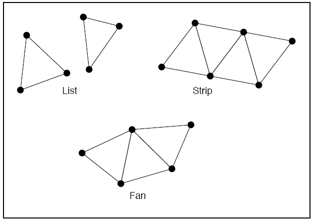
Present函数用于交换前后绘图表面,以实现图形在屏幕的最终显示。
Presents the contents of the next buffer in the sequence of back buffers owned by the device.
Syntax
HRESULT Present(CONST RECT *pSourceRect,
CONST RECT *pDestRect,
HWND hDestWindowOverride,
CONST RGNDATA *pDirtyRegion
);
Parameters
pSourceRect
[in] Pointer to a value that must be NULL unless the swap chain was created with D3DSWAPEFFECT_COPY.
pSourceRect is a pointer to a RECT structure containing the source rectangle. If NULL, the entire source surface
is presented. If the rectangle exceeds the source surface, the rectangle is clipped to the source surface.
pDestRect
[in] Pointer to a value that must be NULL unless the swap chain was created with D3DSWAPEFFECT_COPY.
pDestRect is a pointer to a RECT structure containing the destination rectangle, in window client coordinates.
If NULL, the entire client area is filled. If the rectangle exceeds the destination client area, the rectangle is clipped
to the destination client area.
hDestWindowOverride
[in] Pointer to a destination window whose client area is taken as the target for this presentation. If this value is NULL,
then the hWndDeviceWindow member of D3DPRESENT_PARAMETERS is taken.
pDirtyRegion
[in] Value must be NULL unless the swap chain was created with D3DSWAPEFFECT_COPY. For more information
about swap chains, see Flipping Surfaces and D3DSWAPEFFECT.
If this value is non-NULL, the contained region is expressed in back buffer coordinates. The rectangles within the
region are the minimal set of pixels that need to be updated. This method takes these rectangles into account
when optimizing the presentation by copying only the pixels within the region, or some suitably expanded set of
rectangles. This is an aid to optimization only, and the application should not rely on the region being copied exactly.
The implementation can choose to copy the whole source rectangle.
Return Value
If the method succeeds, the return value is D3D_OK.
If the method fails, the return value can be one of the following:
D3DERR_DEVICELOST The device has been lost but cannot be reset at this time. Therefore, rendering is not possible.
D3DERR_DRIVERINTERNALERROR Internal driver error. Applications should generally shut down when receiving
this error. For more information, see Driver Internal Errors.
D3DERR_INVALIDCALL The method call is invalid. For example, a method's parameter may have an invalid value.
Remarks
If necessary, a stretch operation is applied to transfer the pixels within the source rectangle to the destination
rectangle in the client area of the target window.
Present will fail, returning D3DERR_INVALIDCALL, if called between BeginScene and EndScene pairs unless the
render target is not the current render target (such as the back buffer you get from creating an additional
swap chain). This is a new behavior for Microsoft DirectX 9.0.
看到这里,你是不是快崩溃了?如果你被这些API函数的使用信息搞得快崩溃了,那太好了 ^_^,反正我的大脑已经快溢出了。
好了,我们来看看使用这些API函数能写出什么有用的东西。
需要在工程中设置链接d3d9.lib dxguid.lib dinput8.lib。
由于文件中用到了GE_APP和GE_INPUT这两个类,它们的具体使用说明请参阅 主窗口和DirectInput的封装。
由于本人水平所限,代码中可能存在错误,如若发现,敬请指出。
源码下载
我们要绘制一个平面三角形,来看看basic_triangle.h的定义:
/*************************************************************************************
[Include File]
PURPOSE:
Create basic D3D triangle face.
*************************************************************************************/
#ifndef BASIC_TRIANGLE_H
#define BASIC_TRIANGLE_H
#define CUSTOM_VERTEX_FVF (D3DFVF_XYZRHW | D3DFVF_DIFFUSE)
struct CUSTOM_VERTEX
{
float x, y, z, rhw;
D3DCOLOR color;
};
class TRIANGLE
{
private:
IDirect3D9* _d3d;
IDirect3DDevice9* _d3d_device;
IDirect3DVertexBuffer9* _vertex_buffer;
public:
TRIANGLE();
~TRIANGLE();
bool Create_D3D_Device(HWND hwnd, bool full_screen = true);
bool Init_Vertex_Buffer();
void Render();
void Release_Direct3D();
};
#endif
再来看看basic_triangle的定义:
/*************************************************************************************
[Include File]
PURPOSE:
Create basic D3D triangle face.
*************************************************************************************/
#include "GE_COMMON.h"
#include "basic_triangle.h"
#define WINDOW_WIDTH 800
#define WINDOW_HEIGHT 600
//------------------------------------------------------------------------------------
// Constructor, initialize member data.
//------------------------------------------------------------------------------------
TRIANGLE::TRIANGLE()
{
_d3d = NULL;
_d3d_device = NULL;
_vertex_buffer = NULL;
}
//------------------------------------------------------------------------------------
// Destrcutor, Release direct3D resource.
//------------------------------------------------------------------------------------
TRIANGLE::~TRIANGLE()
{
Release_Direct3D();
}
//------------------------------------------------------------------------------------
// Release direct3D resource.
//------------------------------------------------------------------------------------
void TRIANGLE::Release_Direct3D()
{
Safe_Release(_vertex_buffer);
Safe_Release(_d3d_device);
Safe_Release(_d3d);
}
//------------------------------------------------------------------------------------
// Create direct3D interface and direct3D device.
//------------------------------------------------------------------------------------
bool TRIANGLE::Create_D3D_Device(HWND hwnd, bool full_screen)
{
// Create a IDirect3D9 object and returns an interace to it.
_d3d = Direct3DCreate9(D3D_SDK_VERSION);
if(_d3d == NULL)
return false;
// retrieve adapter capability
D3DCAPS9 d3d_caps;
_d3d->GetDeviceCaps(D3DADAPTER_DEFAULT, D3DDEVTYPE_HAL, &d3d_caps);
bool hardware_process_enable = (d3d_caps.DevCaps & D3DDEVCAPS_HWTRANSFORMANDLIGHT ? true : false);
// Retrieves the current display mode of the adapter.
D3DDISPLAYMODE display_mode;
if(FAILED(_d3d->GetAdapterDisplayMode(D3DADAPTER_DEFAULT, &display_mode)))
return false;
// set present parameter for direct3D device
D3DPRESENT_PARAMETERS present_param = {0};
present_param.BackBufferWidth = WINDOW_WIDTH;
present_param.BackBufferHeight = WINDOW_HEIGHT;
present_param.BackBufferFormat = display_mode.Format;
present_param.BackBufferCount = 1;
present_param.hDeviceWindow = hwnd;
present_param.Windowed = !full_screen;
present_param.SwapEffect = D3DSWAPEFFECT_FLIP;
present_param.PresentationInterval = D3DPRESENT_INTERVAL_DEFAULT;
// Creates a device to represent the display adapter.
DWORD behavior_flags;
behavior_flags = hardware_process_enable ? D3DCREATE_HARDWARE_VERTEXPROCESSING : D3DCREATE_SOFTWARE_VERTEXPROCESSING;
if(FAILED(_d3d->CreateDevice(D3DADAPTER_DEFAULT, D3DDEVTYPE_HAL, hwnd, behavior_flags,
&present_param, &_d3d_device)))
{
return false;
}
// create successfully
return true;
}
//------------------------------------------------------------------------------------
// Initialize vertex buffer with curstom vertex structure.
//------------------------------------------------------------------------------------
bool TRIANGLE::Init_Vertex_Buffer()
{
CUSTOM_VERTEX custom_vertex[] =
{
{ 0.0f, 0.0f, 0.0f, 1.0f, D3DCOLOR_XRGB(255, 0, 0) },
{ WINDOW_WIDTH, 0.0f,10.8f, 1.0f, D3DCOLOR_XRGB(0, 255, 0) },
{ WINDOW_WIDTH, WINDOW_HEIGHT, 30.0f, 1.0f, D3DCOLOR_XRGB(0, 0, 255) }
};
BYTE* vertex_data;
// Creates a vertex buffer.
if(FAILED(_d3d_device->CreateVertexBuffer(3 * sizeof(CUSTOM_VERTEX), 0, CUSTOM_VERTEX_FVF, D3DPOOL_MANAGED,
&_vertex_buffer, NULL)))
return false;
// Locks a range of index data and obtains a pointer to the index buffer memory.
if(FAILED(_vertex_buffer->Lock(0, 0, (void**) &vertex_data, 0)))
return false;
// copy vertex data into buffer
memcpy(vertex_data, custom_vertex, sizeof(custom_vertex));
// unlock vertex buffer
_vertex_buffer->Unlock();
return true;
}
//------------------------------------------------------------------------------------
// Render triangle.
//------------------------------------------------------------------------------------
void TRIANGLE::Render()
{
if(_d3d_device == NULL)
return;
// Clears render target with black
_d3d_device->Clear(0, NULL, D3DCLEAR_TARGET, D3DCOLOR_XRGB(0, 0, 0), 1.0, 0);
// Begins a scene.
_d3d_device->BeginScene();
// Binds a vertex buffer to a device data stream.
_d3d_device->SetStreamSource(0, _vertex_buffer, 0, sizeof(CUSTOM_VERTEX));
// Sets the current vertex stream declaration.
_d3d_device->SetFVF(CUSTOM_VERTEX_FVF);
// render triangle
_d3d_device->DrawPrimitive(D3DPT_TRIANGLELIST, 0, 1);
// end a scene
_d3d_device->EndScene();
// Presents the contents of the next buffer in the sequence of back buffers owned by the device.
_d3d_device->Present(NULL, NULL, NULL, NULL);
}
我们编写一个测试文件来测试,main.cpp的定义:
/*************************************************************************************
[Implement File]
PURPOSE:
Test for triangle draw.
*************************************************************************************/
#define DIRECTINPUT_VERSION 0x0800
#include "GE_APP.h"
#include "GE_INPUT.h"
#include "basic_triangle.h"
#pragma warning(disable : 4996)
int WINAPI WinMain(HINSTANCE instance, HINSTANCE, LPSTR cmd_line, int cmd_show)
{
GE_APP ge_app;
GE_INPUT ge_input;
TRIANGLE triangle;
MSG msg = {0};
// create window
if(! ge_app.Create_Window("Basic triangle draw", instance, cmd_show))
return false;
HWND hwnd = ge_app.Get_Window_Handle();
// create directinput
ge_input.Create_Input(instance, hwnd);
SetWindowPos(hwnd, 0, 0,0,0,0, SWP_NOSIZE);
SetCursorPos(0, 0);
// Create direct3D interface and direct3D device.
if(! triangle.Create_D3D_Device(hwnd, false))
return false;
// Initialize vertex buffer with curstom vertex structure.
if(! triangle.Init_Vertex_Buffer())
return false;
while(msg.message != WM_QUIT)
{
if(PeekMessage(&msg, NULL, 0,0 , PM_REMOVE))
{
TranslateMessage(&msg);
DispatchMessage(&msg);
}
else
{
// read data from keyboard buffer
if(ge_input.Read_Keyboard())
{
// press "R", render triangle.
if(ge_input.Is_Key_Pressed(DIK_R))
triangle.Render();
// press "ESC", close window.
if(ge_input.Is_Key_Pressed(DIK_ESCAPE))
PostQuitMessage(0);
}
}
}
UnregisterClass(WINDOW_CLASS_NAME, instance);
return true;
}
按下R键将绘制一个三角形。
运行效果: