Emissive Lighting (Direct3D 9)
Emissive lighting is described by a single term.
Emissive Lighting = Ce
Where:
| Parameter |
Default value |
Type |
Description |
| Ce |
(0,0,0,0) |
D3DCOLORVALUE |
Emissive color. |
The value for Ce is either:
- vertex color1, if EMISSIVEMATERIALSOURCE = D3DMCS_COLOR1, and the first
vertex color is supplied in the vertex declaration.
- vertex color2, if EMISSIVEMATERIALSOURCE = D3DMCS_COLOR2, and the second
vertex color is supplied in the vertex declaration.
- material emissive color
Note If either EMISSIVEMATERIALSOURCE option is
used, and the vertex color is not provided, the material emissive color is used.
Example
In this example, the object is colored using the scene ambient light and a
material ambient color. The code is shown below.
// create material
D3DMATERIAL9 mtrl;
ZeroMemory( &mtrl, sizeof(mtrl) );

mtrl.Emissive.r = 0.0f;
mtrl.Emissive.g = 0.75f;
mtrl.Emissive.b = 0.0f;
mtrl.Emissive.a = 0.0f;

m_pd3dDevice->SetMaterial( &mtrl );
m_pd3dDevice->SetRenderState(D3DRS_EMISSIVEMATERIALSOURCE, D3DMCS_MATERIAL);
According to the equation, the resulting color for the object vertices is the
material color.
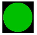
The image below shows the material color, which is green. Emissive light
lights all object vertices with the same color. It is not dependent on the
vertex normal or the light direction. As a result, the sphere looks like a 2D
circle because there is no difference in shading around the surface of the
object.
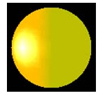
This image shows how the emissive light blends with the other three types of
lights, from the previous examples. On the right side of the sphere, there is a
blend of the green emissive and the red ambient light. On the left side of the
sphere, the green emissive light blends with red ambient and diffuse light
producing a red gradient. The specular highlight is white in the center and
creates a yellow ring as the specular light value falls off sharply leaving the
ambient, diffuse and emissive light values which blend together to make yellow.
Camera Space Transformations (Direct3D 9)
Vertices in the camera space are computed by transforming the object vertices
with the world view matrix.
V = V * wvMatrix
Vertex normals, in camera space, are computed by transforming the object
normals with the inverse transpose of the world view matrix. The world view
matrix may or may not be orthogonal.
N = N * (wvMatrix-1)T
The matrix inversion and matrix transpose operate on a 4x4 matrix. The
multiply combines the normal with the 3x3 portion of the resulting 4x4 matrix.
If the render state, D3DRENDERSTATE_NORMALIZENORMALS is set to TRUE, vertex
normal vectors are normalized after transformation to camera space as follows:
N = norm(N)
Light position in camera space is computed by transforming the light source
position with the view matrix.
Lp = Lp * vMatrix
The direction to the light in camera space for a directional light is
computed by multiplying the light source direction by the view matrix,
normalizing, and negating the result.
Ldir = -norm(Ldir * wvMatrix)
For the D3DLIGHT_POINT and D3DLIGHT_SPOT the direction to light is computed
as follows:
Ldir = norm(V * Lp), where the parameters are defined
in the following table.
| Parameter |
Default value |
Type |
Description |
| Ldir |
N/A |
D3DVECTOR |
Direction vector from object vertex to the light |
| V |
N/A |
D3DVECTOR |
Vertex position in camera space |
| wvMatrix |
Identity |
D3DMATRIX |
Composite matrix containing the world and view transforms |
| N |
N/A |
D3DVECTOR |
Vertex normal |
| Lp |
N/A |
D3DVECTOR |
Light position in camera space |
| vMatrix |
Identity |
D3DMATRIX |
Matrix containing the view transform |